
Subscribe to Our Youtube Channel
Related Manuals for mercor mcr EXi-F


Summary of Contents for mercor mcr EXi-F
- Page 1 FIRE VENTILATION SYSTEMS DEPARTMENT OPERATION AND MAINTENANCE MANUAL Hybrid smoke prevention system for evacuation routes mcr EXi-F mcr EXI-F 23.07.28.1 version...
-
Page 2: Table Of Contents
4.4.3. Requirements concerning the design of a fire ventilation system ..........11 SYSTEM COMPONENTS ........................12 5.1. Design of the mcr EXi-F air supply unit ..................12 5.1.1. Fan ..............................16 5.1.2. Shut-off damper (non-insulated/insulated)................... 17 5.1.3. Service disconnector ........................18 5.1.4. - Page 3 6.1.12. mcr PSR / mcr PSRC manual control panel .................. 74 6.1.13. mcr WPS elevated control panel ....................75 6.1.14. Duct smoke detector ........................75 6.1.15. mcr HT anti-icing system ......................76 6.1.16. Connection of mcr EXi-F actuators ....................76 6.1.16.1. Actuators with return spring ....................76 6.1.16.2.
-
Page 4: Introduction Into Trading
OMM - mcr EXi-F 1. INTRODUCTION INTO TRADING The EXi-F hybrid smoke prevention system for evacuation routes has been introduced into trading based on documents issued by the Instytut Techniki Budowlanej (Construction Technology Institute) and a national declaration of performance: 1. -
Page 5: Foreword
• System mode of operation Operation of the mcr EXi-F system is controlled by the mcr Omega power supply and control panel. The overpressure system is activated automatically by means of a signal from FSS. Once a signal confirming that a fire was detected in the building is sent, the following activities are performed: •... - Page 6 Figure 1 mcr EXi-F system schematic diagram. Where the door to the protected zone is closed, the fan, which is the main element of the air supply unit, delivers the necessary stable air volume. Measurement and control of the current pressure value in the protected space is ensured via one or more pressure transmitters.
-
Page 7: System Selection Principle
The following may be used as system unsealing modules in the mcr EXi-F system: roof exhaust vent with a multi-blade damper with an mcr RPC fire-rated actuator, •... -
Page 8: Requirements Of The En 12101-13 Standard
OMM - mcr EXi-F 4.4.1. Requirements of the EN 12101-13 standard The standard [1] sets apart two pressure differentiation system classes (Class 1 and Class 2) that differ in terms of the design requirements and conditions. The following table presents the typical applications of system classes based on building purpose. -
Page 9: Requirements In The Manual No. 378/2002 Of The Construction Technology Institute
OMM - mcr EXi-F Air supply to the staircase should be distributed evenly over the entire height of the staircase via a vertical shaft. Air supplies should be located at least on every third level, unless the design indicates that a smaller number of supplies will ensure the required throughput. - Page 10 OMM - mcr EXi-F Smoke ventilation of evacuation corridors System class Conditions 1. Direct air supply to the corridor. Air velocity ≤5 m/s. Minimum supply airflow 3600 m3/h. 2. Smoke extraction system throughput ≥130% of the supply throughput. Solution A 3.
-
Page 11: Requirements Concerning The Design Of A Fire Ventilation System
OMM - mcr EXi-F 4.4.3. Requirements concerning the design of a fire ventilation system The standard [1] and Manual [2] determine the requirements that a fire ventilation system should meet. The following table presents the basic guidelines that are to be taken into consideration when designing the system. -
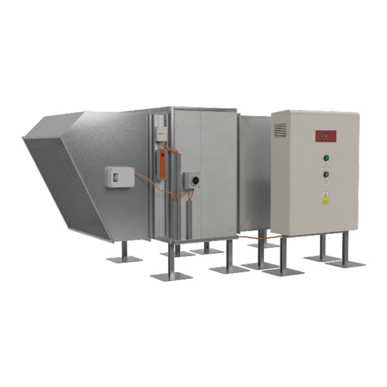
Page 12: System Components
(optional) • anti-icing system (optional). • Figure 3 Design of the mcr mcr EXi-F air supply unit (horizontal version). Figure 4 Design of the mcr mcr EXi-F air supply unit (UP vertical version). Version mcr EXI-F 23.07.28.1 Page 12/99... - Page 13 Figure 6 Sample installation of an air supply kit for the mcr EXi-F system in the duct version: 1 - fan, 2 – damper with actuator, 3 – service disconnector or connection box, 4 - flexible connection, 5 duct smoke detector.
- Page 14 OMM - mcr EXi-F Figure 7 Sample installation of an air supply kit for the mcr EXi-F system in the UP version on the roof: 1 - fan, 2 – LAM vent with actuator, 3 – service disconnector or connection box, 4 – roof base, 5 - duct smoke detector.
- Page 15 Figure 10 Sample installation of an mcr EXi-F air supply unit on the roof with a back-up unit: 1a - air supply unit basic fan, 1b - air supply unit back-up fan, 2 – intake vent, 3 - flexible connection, 4 - dampers with actuators in a double intake vent system, 5 - duct smoke detector, 6 - shut-off damper, 7 - ventilation duct, 8 –...
-
Page 16: Fan
OMM - mcr EXi-F 5.1.1. Fan The mcr EXi-F system air supply units rely on the mcr Monsun E1 fans. Their task is to transport an appropriate volume of air to ensure that the design requirements are met. Fans may be installed indoors or outdoors, with the engine in a horizontal or vertical position. Air supply fans are delivered in a box-type housing version. -
Page 17: Shut-Off Damper (Non-Insulated/Insulated)
5.1.2. Shut-off damper (non-insulated/insulated) Air supply units of the mcr EXI-F system may be equipped with BLF / BF / BFL / BFN / NF / SF or MF / MLF shut-off dampers with actuator (voltage disconnection opens the damper). The damper rotating mechanism consists of bearings and cogs hidden inside the profile. -
Page 18: Service Disconnector
OMM - mcr EXi-F 5.1.3. Service disconnector A service disconnector may be installed on the housing of the mcr Monsun E1 fan. If the mcr EXi-F air supply unit is ordered with a service disconnector, the electric wiring will be routed from the disconnector to the engine connection box at the factory. -
Page 19: Installation Feet (Optional)
It provides a secure system for installing devices. Figure 17 Attachment system overview. 5.1.6. LAM louvered vents (optional) The mcr EXi-F may include a mcr LAM louvered vent that enables the following: evacuation of air or smoke from a building, •... -
Page 20: Explosion Pressure Relief Panels (Pl, Pld) And System Permanent Unsealing Module (Prc) (Optional)
5.2. Explosion pressure relief panels (PL, PLD) and system permanent unsealing module (PRC) (optional) Explosion pressure relief panels in the mcr EXi-F system may be used as an additional air relief from the protected space in cases where it is more difficult to ensure the required system operating parameters. - Page 21 OMM - mcr EXi-F Basic dimensions and throughput [m3/h] of the mcr PL explosion pressure relief panel Width B [mm] Height A [mm] 1000 1100 1200 1300 4050 4880 5700 6500 7300 8150 9000 9800 10,600 4880 5860 6800 7800...
- Page 22 OMM - mcr EXi-F The protected space mcr RPC unsealing module is designed for use in sealed spaces protected with an overpressure system. The mcr RPC unsealing module eliminates pressure hikes in the protected space that occur during evacuation as a result of closing doors. mcr RPC includes the following elements: roof exhaust vent, multi-blade damper with a 24 V actuator and a roof base.
-
Page 23: Mcr Omega Control Panel
5.3. mcr OMEGA control panel 5.3.1. Description and principle of operation mcr EXi-F pressure differentiation systems rely on an mcr OMEGA panel, adjusted for digital pressure control or ensuring a steady flow rate. Digital pressure control is ensured via the predictive mcr ICR Pro regulator, which ensures appropriate adjustment of the system operating parameters to varying evacuation conditions. - Page 24 OMM - mcr EXi-F Figure 22 mcr Omega control panel overview. Dimensions (standard version) of mcr Omega control panels mcr Omega control Width W [mm] Height H [mm] Depth [mm] panel type 63.1 71.1 71.3 80.4 90.5 90.7 1000 100.11 1000 100.15...
-
Page 25: Signaling
OMM - mcr EXi-F 5.3.2. Signaling The panel signals the following operating conditions: monitoring (green), • fire alarm (red), • blocked (blinking yellow), • fault (solid yellow). • 5.3.3. Specifications mcr OMEGA control panel specification Basic supply voltage 400V AC +10%. –15%, 50Hz Panel working voltage 22.5 V ..32 V AC(24 V at 200C) - Page 26 OMM - mcr EXi-F List of product (component) types depending on system configuration Product type designation Control board mcr EXi-F 100-1S mcr Monsun E1 100-4T-20 mcr OMEGA 100.15 mcr EXi-F 100-2S mcr Monsun E1 100-4T-15 mcr OMEGA 100.11 mcr EXi-F 90-1S mcr Monsun E1 90-4T-10 mcr OMEGA 90.7...
-
Page 27: Mcr Icr Pro Positive Pressure Regulator
OMM - mcr EXi-F 5.3.4. mcr ICR pro positive pressure regulator The regulator for smoke and heat control systems is an element of the mcr Omega panel that controls the rpm of the fan via a three-phase frequency converter in order to maintain the desired constant positive pressure value (20-80 Pa) in the protected zone (the device is located in the mcr Omega control panel). -
Page 28: Mcr Ics Pro Differential Pressure Transmitter
OMM - mcr EXi-F For one mcr ICS pro regulator. Communication between system components is ensured via the mcr BUS, which provides high throughput and a high level of security. mcr BUS is a multi-master bus, which in practice means that each device connected to the bus is able to send data at any time, so that individual transmitters can immediately inform the controller that a fault has been detected or an alarm signal has been received. - Page 29 OMM - mcr EXi-F Multi-channel bushing Figure 23 mcr ICS pro digital pressure transmitter - overview. The device offers two inputs that receive silicone pneumatic hoses leading to zones where the pressure difference is to be measured. These are marked on the PCB cover as P1 and P2.
-
Page 30: Mcr Psr / Mcr Psrc Manual Control Panel
OMM - mcr EXi-F 5.5. mcr PSR / mcr PSRC manual control panel An elevated manual control panel is used to control the system from a distance using a key switch. It allows the lead firefighter to manually activate or deactivate the pressurization smoke control system. -
Page 31: Mcr Wps Elevated Control Panel
OMM - mcr EXi-F PSR/PSRC technical parameters Hard-wired, Connecting to the mcr OMEGA panel multicore cable (PSR) or digital (PSRC) Housing ingress protection: IP 44 Cam switch with key, 3 positions Control method: (0-AUTO, I – TEST, II – STOP) -
Page 32: Duct Smoke Detector
OMM - mcr EXi-F Figure 26 Overview of an elevated control panel with visualization. Elevated technical panel with visualization technical parameters Power supply 230[V], AC +10%. –15%, 50Hz Protection Internal overcurrent circuit breakers Basic dimensions 600 mm x 400 mm x 200 mm... -
Page 33: Intake Vent Switching System
OMM - mcr EXi-F Figure 27 SDD-65-RAC duct smoke detector - overview. 5.8. Intake vent switching system When air inlets are located at the roof level, two air inlets (two intake vent system) should be used, placed at a distance and facing different directions, so that they cannot be located directly leeward of the same source of smoke. -
Page 34: Mcr Icp Lobby Controller
OMM - mcr EXi-F Figure 28 Sample installation of an air supply kit for the mcr EXi-F system in the roof-mounted version with two air intake vents: 1 - fan, 2 – intake vent, 3 – flexible connection, 4 – dampers with actuators in a double intake vent system, 5 –... - Page 35 OMM - mcr EXi-F POWER SUPPLY FAILURE Figure 29 mcr ICP regulator overview (dimensions • Without glands and controls: 340 mm x 270 mm x 106 mm, with glands and indicator lights: 367 mm x 270 mm x 120 mm).
- Page 36 OMM - mcr EXi-F Figure 30 Connections circuit diagram for the Belimo NMQ/LMQ/SMQ series actuator. An example connection diagram is presented in Figure 31. Actuators are connected to the regulator only through a dedicated connection box. The box is equipped with a thermal fuse. The total length of cables between the regulator and the actuator must not exceed 15 m.
-
Page 37: Mcr Pp Connection Box
Without calibration, the device will not respond to signals from the FSS system. Configuration and adjustment of the regulator is performed by authorized "MERCOR" S.A. service. 5.10. mcr PP connection box Connecting actuators to the controller can be done through a dedicated connection box. The box is equipped with a thermal fuse. -
Page 38: Damper For Lobby Systems
Figure 33 Terminals in the mcr PP box. 5.11. Damper for lobby systems mcr EXI-F system air supply units may be equipped with multi-blade control dampers (mcr EPSCR- A, mcr EPSCR-B) with LMQ/NMQ/SMQ24A-SR actuators. The damper rotating mechanism consists of bearings and cogs hidden inside the profile housing or provided in the form of steel tendons. -
Page 39: Mcr Ht Anti-Icing System
5.12. mcr HT anti-icing system The mcr HT kit is used to protect mcr EXi-F air supply units from blockage due to icing. The system uses 500 W directional infrared radiators, with additional radiators available if needed. The system is controlled by a thermostat. - Page 40 OMM - mcr EXi-F Optional component - not necessary for proper mcr EXi-F system operation WZ - power cable provided by the customer PP – connection box on the fan facade W1, W2, W3 - OLFLEX HEAT 180 SiHF 3G2.5 cables...
-
Page 41: Mcr Sep Network Separators
OMM - mcr EXi-F 5.13. mcr SEP network separators In the case of large-area facilities, where the distance between the subsequent elements of the communication loop is more than 250 m, mcr SEP network separators are used to prevent network signal fading. -
Page 42: Temperature Transmitter
PC, PS, ABS 5.14. Temperature transmitter Pressure transmitters in the mcr EXi-F system are used to determine the flow direction of air in reversing systems. "MERCOR" S.A. offers 2 types of transmitters: MB series and AR series. Figure 40 Overview and connection details for the MB series temperature transmitter. -
Page 43: Magnetic Sensors (Reeds)
OMM - mcr EXi-F terminals description power input 9...36 V dc; 9...28 V ac rS485 interface lines - RS jumper terminating the RS485 interface line with a 120 Ω resistor (termination enabled when JP1 is shorted) 5.15. Magnetic sensors (reeds) Magnetic sensors can be used in mcr Omega panels to control the position of doors and windows. -
Page 44: Electrical Connection
Figure 44 Electrical diagram of a LF or DW series differential pressure switch. 6. ELECTRICAL CONNECTION mcr EXI-F system elements require the proper power supply that will guarantee delivery of a control signal or voltage to the device in case of fire. An electrical connection should be performed exactly as indicated by the attached diagram and in accordance with the guidelines presented under section 5 of this documentation. - Page 45 OMM - mcr EXi-F applicable regulations. Any inspection works concerning the system should only be performed after disconnecting the device from the power supply. A sample electric connection diagram for a typical system is presented in the figure below. Figure 45 General electrical connection diagram for the EXi-F system: electrical connection, suggested types of wires for the mcr Omega control panel.
- Page 46 OMM - mcr EXi-F Figure 46 Electrical connection diagram for the mcr ICP lobby regulator handling 2 corridors and 4 high- speed dampers. The lobby regulator handles between 2 and 4 dampers, as well as smoke control system vents installed on air supply ducts and may control smoke control system vents installed on a high-speed damper system.
- Page 47 OMM - mcr EXi-F EXi-F AIR SUPPLY UNIT anti-icing damper system* service duct smoke inlet nozzle disconnector detector Control board mcr Omega air flow direction mcr ICS pro digital pressure transmitter (Caution: Installation with the hoses downwards!) Pressure measurement point...
- Page 48 OMM - mcr EXi-F damper double intake vent - normally closed inlet nozzle or intake vent damper double intake vent - normally open damper inlet nozzle or intake vent duct smoke Control board detector mcr Omega air flow air flow...
- Page 49 OMM - mcr EXi-F SUGGESTED WIRING Designation on Connections of automation components Cable type the diagram 3x400 V uninterruptible power supply cable for the NHXCH FE180/PH90 4x designed cross-section EXi-F FAN 3x400 V uninterruptible power supply cable for TS NHXH 5x designed cross-section...
- Page 50 OMM - mcr EXi-F Key: SRC high-speed damper Damper Smoke control vent Static differential pressure measurement - Ø8 pulse lines Duct smoke detector Digital pressure regulator Caution! Installation with pressure hoses downwards Digital pressure transmitter Caution! Installation with pressure hoses downwards...
- Page 51 OMM - mcr EXi-F Figure 49 Schematic wiring diagram for a basic unit. Version mcr EXI-F 23.07.28.1 Page 51/99...
- Page 52 OMM - mcr EXi-F Figure 50 Schematic wiring diagram for a basic unit with a two intake vent system. Version mcr EXI-F 23.07.28.1 Page 52/99...
- Page 53 OMM - mcr EXi-F Figure 51 Schematic wiring diagram for a unit with the mcr HT anti-icing system. Figure 52 Schematic wiring diagram for a unit with a double intake vent system and mcr HT anti-icing system. Version mcr EXI-F 23.07.28.1...
- Page 54 OMM - mcr EXi-F Figure 53 Schematic diagram of a vertical unit with a mcr LAM vent. Version mcr EXI-F 23.07.28.1 Page 54/99...
- Page 55 OMM - mcr EXi-F Figure 54 Schematic wiring diagram for lobby air supply. Version mcr EXI-F 23.07.28.1 Page 55/99...
- Page 56 OMM - mcr EXi-F Figure 55 Schematic wiring diagram for a unit with high-speed mcr ICP dampers secured with smoke control system vents. Version mcr EXI-F 23.07.28.1 Page 56/99...
- Page 57 OMM - mcr EXi-F Figure 56 Schematic wiring diagram for a unit with high-speed mcr ICP dampers secured with smoke control system vents located at a higher distance from the regulator, using an mcr PP box. Version mcr EXI-F 23.07.28.1...
- Page 58 OMM - mcr EXi-F Figure 57 Schematic diagram for connecting four high-speed dampers to the mcr ICP high-speed damper regulator thorough a mcr PP box. Version mcr EXI-F 23.07.28.1 Page 58/99...
- Page 59 OMM - mcr EXi-F 24 V DC power supply unit Optional 24 V DC power supply from another fire power supply unit e.g. mcr Omega pro Figure 58 Block diagram for connecting a mcr ICS Pro pressure transmitter in a staircase-single transmitter setup.
- Page 60 OMM - mcr EXi-F ICSpro no. 1 ZTS Omega or 24 V DC 5 W uninterruptible power supply pressure transmitters in a staircase system with the underground ICSpro no. 2 ZTS Omega or 24 V DC 5 W uninterruptible power supply Figure 60 Block diagram for connecting mcr ICS Pro pressure transmitters in a staircase system with separate transmitters in the underground part triggered from the FSS.
- Page 61 OMM - mcr EXi-F ICSpro no. 1 ICSpro no. 24 (max) 24 V DC 5 W 24 V DC 5 W uninterruptible uninterruptible power supply power supply ICSpro no. n+1 ICSpro no. n 24 V DC 5 W 24 V DC 5 W...
-
Page 62: Electrical Connections Of Devices To The Mcr Omega Panel
Electrical connections of devices to the mcr Omega panel 6.1.1. EXI-F unit air supply fan Control panels are dedicated automation systems (selected based on the fan power) for each mcr EXI-F air supply unit. Detailed connection diagrams are provided with each control panel in the form of an attached document and stickers on the internal side of the mcr Omega cabinet door. -
Page 63: Service Disconnector
Figure 64 Step by step wire preparation guide. 6.1.2. Service disconnector mcr EXI-F air supply units may be equipped with service disconnectors, which are used to disconnect power supply to the fan if an inspection or maintenance is necessary. electromotive 3-position service disconnector Figure 65 Electrical diagram of the service disconnector for the air supply unit fan. -
Page 64: Mcr Pld Explosion Pressure Relief Panels
OMM - mcr EXi-F 24 V actuator Actuator monitoring M1 fan damper M1 fan damper (normally closed) "top" and "bottom" limit switch Figure 66 Shut-off damper actuator connections circuit diagram. 6.1.4. mcr PLD explosion pressure relief panels As standard, devices are equipped with multi-blade dampers (material: aluminum, type: reverse- action) with an actuator (type: BF /BFL /BFN, 24 V DC power supply), which are used as elements that counteract the free flow of air while the devices are not in operation. -
Page 65: Connection Of The Mcr Omega Control Panel From Fss
OMM - mcr EXi-F 24 V actuator Actuator monitoring RPC damper RPC damper (normally closed) "top" and "bottom" limit switch Figure 68 mcr RPC connections circuit diagram. 6.1.6. Connection of the mcr Omega control panel from FSS SSP signal fire alarm open contact=alarm Figure 69 Connection of SSP signal (fire ALARM) to the EXi-F panel. -
Page 66: Connection Diagram For Automation With Backup Fan
OMM - mcr EXi-F panel panel panel Signal to SSP: Signal to SSP: Signal to SSP: Execution of the Activation from Panel fire alarm the manual collective procedure control panel failure Contact closed = SSP Signal: Contact closed = RESET... -
Page 67: Automation Connection Diagram For Vertical Fans
OMM - mcr EXi-F 6.1.8. Automation connection diagram for vertical fans Air supply fan Figure 73 Fan connections circuit diagram LEM vent 24VDC Vent opening - "+" - brown, "-" - blue Vent opening - brown, - blue Vent closing - "-" - brown, "+" - blue Vent closing - - brown "+"... -
Page 68: Automation Connection Diagram For Switching System / Double Intake Vent
OMM - mcr EXi-F 6.1.9. Automation connection diagram for switching system / double intake vent Damper Damper NO intake vent NC intake vent damper damper (normally open) (normally closed) Figure 75 Connections circuit diagram for two dampers in the intake vent switching system. - Page 69 OMM - mcr EXi-F mcr ICP CONNECTION BOX Corridor damper 2 Explosion pressure relief panel Lobby damper 1 Lobby damper 2 Corridor damper 1 Figure 76 General block diagram for connecting mcr ICP and mcr PP regulators (support for 4 lobby dampers).
- Page 70 OMM - mcr EXi-F DAMPER_SRC_1 DAMPER_SRC_2 DAMPER_SRC_3 DAMPER_SRC_4 Figure 77 Block diagram for connecting a mcr ICP regulator in the communications network with mcr Omega. Version mcr EXI-F 23.07.28.1 Page 70/99...
- Page 71 OMM - mcr EXi-F Collective failure 1 Power supply 24 volts DC Contact closed = failure Fire Fire (normally closed) (normally closed) Figure 78 Block diagram for connecting a mcr ICP regulator – option with support for fire ventilation vents.
- Page 72 Without calibration, the device will not respond to signals from the FSS system. The above works are performed by authorized "MERCOR" S.A. service. NMQ/LMQ/SMQ actuators are installed in the case of dampers used for lobby systems, where high- speed dampers are used.
-
Page 73: Mcr Ics Pro Differential Pressure Transmitter
OMM - mcr EXi-F 6.1.11. mcr ICS pro differential pressure transmitter Route the shield up to the gland Power Supply Unit SSP signal If there is no signal 24 V DC depending on from the SSP, connect system a 10 kΩ resistor into... -
Page 74: Mcr Psr / Mcr Psrc Manual Control Panel
OMM - mcr EXi-F 6.1.12. mcr PSR / mcr PSRC manual control panel yellow green green If mcr PSR is not connected, install a 10 kΩ resistor between pins 6 and 8, as well as 7 and 8 Figure 81 mcr PSR manual control panel connections circuit diagram. -
Page 75: Mcr Wps Elevated Control Panel
NC intake vent opening 9,10 opened = closing 9,10 opened = MALFUNCTION MALFUNCTION Optional component - not necessary for proper mcr EXi-F system operation Figure 84 UG-3-A4 duct smoke detector connections circuit diagram. Version mcr EXI-F 23.07.28.1 Page 75/99... -
Page 76: Mcr Ht Anti-Icing System
Figure 86 Electrical connection of the mcr Omega panel for the anti-icing system. 6.1.16. Connection of mcr EXi-F actuators 6.1.16.1. Actuators with return spring Figure 87 Connections circuit diagram for the Belimo BF/BFL/BFN series actuator. Actuators used in shut-off dampers at mcr EXI-F air supply units. Version mcr EXI-F 23.07.28.1 Page 76/99... -
Page 77: Actuators Without Return Spring
OMM - mcr EXi-F 6.1.16.2. Actuators without return spring Figure 88 Connections circuit diagram for the Belimo BE/BEE/BLE series actuator. Actuators used in dampers in double intake vent systems. 6.1.16.3. High-speed actuators for the mcr ICP lobby regulator Figure 89 Connections circuit diagram for the Belimo NMQ/LMQ/SMQ series actuator. - Page 78 OMM - mcr EXi-F VESTIBULE CORRIDOR STAIRCASE ELEVATOR air supply unit with damper and smoke detector pressure measurement point located in the usable floor space mcr RPC protected space unsealing module (optional) PSR manual control panel mcr Omega control panel(s)
-
Page 79: Connection Of A Mcr Ics Pro Differential Pressure Transmitter
OMM - mcr EXi-F When pressure measurement points are located at a significant distance from the pressure transmitter, an additional set of hoses with a length of 5 m and a diameter of 8 mm may be used (maximum total length of pressure hoses should not exceed 12 m). An additional set of hoses is equipped with 4 connecting elements (2 elbow connectors, 2 straight connectors). -
Page 80: Connecting The Mcr Icp Lobby Regulator
OMM - mcr EXi-F 7.2. Connecting the mcr ICP lobby regulator The device offers two input pairs that receive silicone hoses leading to zones where the pressure difference is to be measured. The first two connections on the right are for zone 1 (P1 upper input, P2 lower input), while the other two connections are for zone 2 (P3 upper input, P4 lower input). -
Page 81: Mechanical Connection Of System Components
Figure 95 Sample standard horizontal installation of a set of mcr EXi-F system components: 1 - fan inlet protection, 2 – damper, 3 – mcr Monsun E1 fan in a box-type housing 4 – ventilation duct (pipe), 5 – flexible connection, 6 –... - Page 82 OMM - mcr EXi-F Flexible connection Flexible Inlet nozzle stub Damper Figure 96 Basic dimensions of the standard mcr EXi-F 63-1 air supply units in a box-type housing - horizontal installation. Flexible connection Flexible Inlet nozzle stub Damper Figure 97 Basic dimensions of the standard mcr EXi-F 80-1S, 71-1S, 71-2S air supply units in a box-type housing - horizontal installation.
- Page 83 TOP VIEW mcr LAM louvered vent (closed) SECTION A-A (vent open) Roof base Figure 100. Vertical installation with louvered vent: mcr EXi-F 71-1S UP, 71-2S UP, 80-1S UP. SECTION B-B TOP VIEW mcr LAM louvered vent (closed) SECTION A-A (vent open) Roof base Figure 101 Vertical installation with louvered vent: mcr EXi-F 90-1S UP,90-2S UP,100-1S UP,100-2 S UP.
-
Page 84: Control Panel Mcr Omega
700x700 mcr EXi-F 70-1S UP, 70-2S UP, 80-1S UP 900x900 mcr EXi-F 90-1S UP, 90-2S UP, 100-1S UP, 100-2S UP 1100x1100 8.2. Control panel mcr Omega As a standard, the control panel is attached to the wall using installation studs or to installation systems using 4xM10 screws. -
Page 85: Mcr Psr / Mcr Psrc Manual Control Panel
OMM - mcr EXi-F 8.4. mcr PSR / mcr PSRC manual control panel Figure 103 Dimensions of available mcr PSR/PRSC installation holes. PSR may be installed with the sides adjacent - housings have beveled openings for wires that may be routed between panels. -
Page 86: Mcr Icp Lobby Regulator
OMM - mcr EXi-F 8.6. mcr ICP lobby regulator Figure 105 Dimensions of mcr ICP regulator installation holes. 8.7. mcr PP connection box Figure 106 Dimensions of mcr PP connection box installation holes. Version mcr EXI-F 23.07.28.1 Page 86/99... -
Page 87: Magnetic Sensors (Reeds)
OMM - mcr EXi-F mcr SEP network separators Figure 107 Dimensions of mcr SEP network separator installation holes. 8.8. Magnetic sensors (reeds) Figure 108 K-x series sensor installation dimensions. 109 Installation dimensions of MC-240 series sensors. Figure Version mcr EXI-F 23.07.28.1... -
Page 88: Differential Pressure Switch
Pressure input P2 (-) is connected upstream from the fan. Figure 110 Installation diagram of a LF series differential pressure switch. 9. ACTIVATION OF THE MCR EXI-F SYSTEM All devices operating in a mcr BUS loop must be marked with the same version. Detection of a device with a different version will result in the system reporting an error. -
Page 89: Mcr Exi-F Application
OMM - mcr EXi-F 9.1. mcr EXi-F application Computer software prepared for working with mcr EXiF system equipment allows for the initial configuration and diagnostics within the following scope: configuration of the operating mode and parameters - including installation diagram, •... -
Page 90: Commissioning, Adjustments, Measurements
To access the application, please contact your account manager. 9.2. Commissioning, adjustments, measurements In order for the mcr EXi-F system to operate properly, it must be commissioned according to the guidelines of Mercor S.A., which include a proper commissioning procedure, allowing for subsequent adjustment and measurements stages, which impact the stability and efficiency of the entire system, to be started seamlessly. - Page 91 All the pressure measurement points must be installed and connected to the pneumatic system as per the mcr EXI-F system OMM Power supply must be provided to all mcr EXI-F system devices (400 V AC, 230 V AC, 24 V AC)
-
Page 92: Most Common Errors
EXi-F system components. The following items indicate the most common errors. Proper operation of each vents in the system should be inspected and confirmed, as well as whether the vents operate in accordance with the fire scenario 2. - Page 93 The pneumatic system may be extended, but appropriate notice must be given to „MERCOR” S.A. Below are example of incorrect and correct (using connection elements) cases of changing tubing directions.
- Page 94 OMM - mcr EXi-F 6. Pressure measuring points - reference, must be unobstructed (e.g. painting tape removed). If there are several mcr ICS Pro transmitters on a floor, check that the measuring points corresponding to the respective protected spaces (e.g. staircases, lobbies, elevators) are connected correctly.
- Page 95 (replacement not covered by the guarantee). Batteries should only be connected once the final power supply is connected. Batteries can be connected by "MERCOR" service during system adjustment. Version mcr EXI-F 23.07.28.1 Page 95/99...
-
Page 96: System Elements Marking Scheme
OMM - mcr EXi-F 10. SYSTEM ELEMENTS MARKING SCHEME mcr EXi-F 1_2_3_ 4_5_6_7_8_9_10_11_12_13_14_15_16_17_18_19_20_21_22_23_24_25_26_27_28_29 Position Symbol Explanation 100-1S 100-2S 90-1S 90-2S air supply unit type 80-1S 71-1S 71-2S 63-1S mcr Monsun E1 fan in a box-type housing, with UP vertical fan... -
Page 97: Transport And Storage Conditions
If possible, ensure that the device is isolated. Air supply units with additional elements (duct smoke detectors, shut-off dampers) of the mcr EXi-F system are placed on pallets (for .the duration of transport and storage). During loading and transportation, the packaging should not be thrown nor knocked over. -
Page 98: Maintenance And Service
In matters related to technical inspections, maintenance and service of equipment, please contact the „MERCOR” S.A. Service Department at serwis@mercor.com.pl, tel. 058/ 341 42 45 w. 170 or fax 058/ 341 39 85 between 8 a.m. and 4 p.m. (Monday to Friday). - Page 99 Where it is impossible to repair equipment at its installation site, "MERCOR" S.A. reserves the right to remove the equipment, have it delivered to the address indicated by "MERCOR" S.A. and have it reinstalled. The cost of these activities shall be the responsibility of the Buyer/party authorized under the guarantee.
Need help?
Do you have a question about the mcr EXi-F and is the answer not in the manual?
Questions and answers