Table of Contents
Advertisement
Quick Links
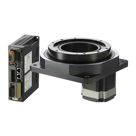
Hollow Rotary Actuator
DGII Series
OPERATING MANUAL
1
Introduction ................................................ 2
2
Safety precautions ..................................... 9
3
Precautions for use .................................. 12
4
Installation ................................................ 15
5
Connection ................................................ 27
6
Maintenance and inspection ................. 32
7
Standards, general specifications ......... 33
8
Power supply current capacity .............. 35
9
Accessories ................................................ 38
Thank you for purchasing an Oriental Motor product.
This Operating Manual describes product handling procedures and safety precautions.
• Please read it thoroughly to ensure safe operation.
• Always keep the manual where it is readily available.
Actuator
HL-80002-9
Advertisement
Table of Contents

Related Manuals for Oriental motor DGM130R


Summary of Contents for Oriental motor DGM130R
-
Page 1: Table Of Contents
Standards, general specifications ..33 Power supply current capacity ....35 Accessories ..........38 Thank you for purchasing an Oriental Motor product. This Operating Manual describes product handling procedures and safety precautions. • Please read it thoroughly to ensure safe operation. -
Page 2: Introduction
The product described in this manual has been designed and manufactured to be incorporated in general industrial equipment. Do not use for any other purpose. Oriental Motor Co., Ltd. is not responsible for any damage caused through failure to observe this warning. - Page 3 Introduction Checking the product Verify that the items listed below are included. Report any missing or damaged items to the Oriental Motor sales office from which you purchased the product. When purchasing a hollow rotary actuator and driver package When purchasing a hollow rotary actuator only •...
- Page 4 Introduction z Actuators equipped with the AR Series D G 1 3 0 R - A R A C D 2 -3 Series name DG: DGII Series 60: 60 mm (2.36 in.) 85: 85 mm (3.35 in.) Frame size 130: 130 mm (5.12 in.) 200: 200 mm (7.87 in.)
- Page 5 Actuators equipped with the AZ Series Motor vertical mounting D G M 1 3 0 R - A Z A C R Series name DGM: DGII Series 60: 60 mm (2.36 in.) 85: 85 mm (3.35 in.) Frame size 130: 130 mm (5.12 in.)
- Page 6 Actuators equipped with the AZ Series Motor horizontal mounting D G B 8 5 R 1 8 - A Z A C R Series name DGB: DGII Series 85: 85 mm (3.35 in.) Frame size 130: 130 mm (5.12 in.)
- Page 7 Introduction z Actuators equipped with the RKII Series D G M 1 3 0 - 5 P K E A C Series name DGM: DGII Series 85: 85 mm (3.35 in.) Frame size 130: 130 mm (5.12 in.) Equipped motor...
- Page 8 Introduction „ DGM85, DGM130, DGM200 This figure shows the DGM130R-AZMC. Load-mounting positioning For the model DGM130R-ARMC Output table pin holes (2 places) that equipped with the AR Series Load-mounting screw holes (6 places) Positioning pin holes (2 places) Shielded plate xed Mounting holes screw holes (2 places) Motor...
-
Page 9: Safety Precautions
Safety precautions Safety precautions The precautions described below are intended to prevent danger or injury to the user and other personnel through safe, correct use of the product. Use the product only after carefully reading and fully understanding these instructions. In regard to a hollow rotary actuator (hereinafter referred to as actuator), it is prohibited to start operating the actuator (i.e., to operate the device in accordance with the specified purpose) when the machine in which the actuator is incorporated does not satisfy any relevant safety standards. - Page 10 Safety precautions • Assign qualified personnel to the task of installing, wiring, operating/controlling, inspecting and troubleshooting the product. Failure to do so may result in fire, electric shock, injury or damage to equipment. • Take measures to keep the moving part in position if the product is used in vertical operations such as elevating equipment.
- Page 11 Safety precautions • Do not use the product beyond its specifications. Doing so may result in electric shock, injury or damage to equipment. • Keep your fingers and objects out of the openings in the product. Failure to do so may result in fire, electric shock or injury. •...
-
Page 12: Precautions For Use
Be sure to use our cable to connect the actuator and the driver. In the following cases, purchase our cable separately. Check on the Oriental Motor Website for the model name. • If a flexible cable is to be used. - Page 13 Precautions for use „ Temperature z Use the actuator equipped with the AZ Series in a conditions where the motor surface temperature does not exceed 80 °C (176 °F). The motor surface temperature may exceed 80 °C (176 °F) under certain conditions (ambient temperature, operating speed, duty cycle, etc.).
- Page 14 Precautions for use „ Notes when the connection cable is used Note the following points when our cable is used. z When inserting the connector Hold the connector main body, and insert it in straight securely. Inserting the connector in an inclined state may result in damage to terminals or a connection failure.
-
Page 15: Installation
Installation Installation Location for installation The actuator has been designed and manufactured to be incorporated in general industrial equipment. Install it in a well-ventilated location that provides easy access for inspection. The location must also satisfy the following conditions: • Inside an enclosure that is installed indoors (provide vent holes) •... - Page 16 Installation „ Installing the DGM60 equipped with the AZ Series The encoder (ABZO sensor) of the DGM60 equipped with the AZ Series is easily affected by a magnetic field, so make sure the installation location. When motors are installed side by side, ensure distances in horizontal and vertical directions of more than the frame size of the other motor installed.
- Page 17 Installation z Releasing procedure 1. Connect the "electromagnetic brake cable" and “cable for electromagnetic brake. ” 2. Connect the lead wires of the “cable for electromagnetic brake” to the 24 VDC power supply. Connect the white lead wire to the +24 VDC terminal, and the black lead wire to the GND terminal. 3.
- Page 18 Installation „ When a mounting plate with cutout is used This figure shows the DGM60-ARAK. z When the positioning pin holes are used as mounting holes Screws (M4) Spring washers Positioning pin holes Positioning pin holes (2 places) (2 places) Motor Positioning pins Screw hole machining...
- Page 19 Installation z Installation method This figure shows the DGM60-AZAK. 1. Pass the motor/encoder lead wires through the through hole of the mounting plate. Motor/encoder lead wires Positioning pins Screw hole machining Through hole in a mounting plate 2. Move the actuator to the through hole which diameter is larger, and secure the mounting holes with screws (two pieces).
- Page 20 Installation Mounting hole Positioning pin hole Model Nominal Pin hole diameter Tightening torque Pin hole diameter Pin hole depth size + 0.015 ø8 8 mm (0.31 in.), DGM200 ø11 mm (ø0.43 in.) 25 N·m (220 lb-in) + 0.0006 (ø0.3150 in.) Blind hole z Positioning pin holes (viewing from the motor side) DGM85, DGM130...
- Page 21 Installation „ When a mounting plate with through-hole is used z Design for mounting plate [reference] [unit: mm (in.)] DGM85 78 (3.07) 70 (2.76) ø5 ( +0.012 ) × deep 5 50 (1.97) [ø0.1969 ( ) × deep 0.20] +0.0005 Details of section A (2:1) 4×M6 DGM130...
- Page 22 Installation DGM200 170 (6.69) 130 (5.12) 102 (4.02) 65 (2.56) +0.015 2×ø8 ( ) × deep 5 +0.0006 [2×ø0.315 ( ) × deep 0.20] 4×M10 z When installing an actuator which cable outlet direction is downward The figure shows the DGM130R-AZAC. Be sure to install the actuator from the upper side of the mounting plate.
- Page 23 Installation 2. Move the actuator to the through hole which diameter is larger, and secure the mounting holes with screws (four pieces). Screws Spring washers Positioning pin holes (2 places) Mounting holes (4 places) z When installing an actuator which cable outlet direction is rightward or leftward This section explains based on an example when the cable outlet direction is rightward.
- Page 24 Installation 3. Secure the mounting holes with screws (four pieces). Screws Spring washers Mounting holes (4 places) Positioning pin holes (2 places) Installation method of DGB85 and DGB130 types Provide screw hole machining in the mounting plate when installing the actuator. Use two positioning pin holes when positioning the actuator.
- Page 25 Installation z Installation method The figure shows the DGB85R18-AZACR. Screws Spring washers Positioning pin holes (2 places) Mounting holes (4 places) Positioning pins Screw hole machining in a mounting plate • Be sure to install the actuator from the upper side of the mounting plate. It cannot be installed from below the mounting plate.
- Page 26 Installation Permissible moment, permissible axial load The permissible moment and permissible axial load should not exceed the permissible value specified in the table. Calculate the axial load and load moment using the International System of Units (N, N·m). Model Output table supporting bearing Permissible moment Permissible axial load DGM60...
-
Page 27: Connection
Connection Connection Connecting the driver Refer to the operating manual of the driver for how to connect with the driver. Grounding the actuator Use a round terminal when grounding, and make sure to secure with a screw and washer. Ground wires and crimp terminals are not included. - Page 28 Connection 2) Grounding the grounding wire of the motor [AC power input type only] Connect the grounding wire of the "cable for motor" to the Protective Earth Terminal of the driver. • Tightening torque: 1.2 N·m (170 oz-in) Cable for motor Connect the grounding wire to the driver Protective Earth Terminal.
- Page 29 Connection „ Installing the home-sensor Do not install the home-sensor set while the power is being supplied. Doing so may result in injury or damage to equipment. • Be sure to install the sensor and shielded plate in the direction shown in the figure. Installing them in the wrong direction may disable sensor detection or cause the shielded plate to contact the sensor, resulting in sensor damage.
- Page 30 Connection • Do not connect or remove the flexible cable with connector while the power is being supplied. Doing so may cause damage to the sensor. • Wire the flexible cable in such a way that it will not contact the actuator. When removing the flexible cable with connector, pull out the connector while pressing it firmly from the top and bottom.
- Page 31 Connection „ Connection example The connection example is shown based on the following conditions. • Return-to-home mode: 3-sensor mode • HOMES output logic: Normally open • Driver: AR Series FLEX Built-in Controller Type z Home-sensor set PADG-SBY (PNP type) PADG-SBY (PNP type) 24 VDC Brown...
-
Page 32: Maintenance And Inspection
Inspection This chapter explains the maintenance items in order to operate an actuator safely and efficiently. If an abnormal condition is noted on the actuator, discontinue any use and contact your nearest Oriental Motor sales office. „ Inspection interval If the actuator is operated eight hours a day, perform maintenance according to the applicable period specified in the table. -
Page 33: Standards, General Specifications
Standards, general specifications Standards, general specifications Standards „ UL Standard and CSA Standard Check the "APPENDIX UL Standards" of each product for recognition information about UL Standards of the equipped motor. „ EU Directives z CE Marking Low Voltage Directive Motors of AC power input type are affixed the CE Marking under the Low Voltage Directive. - Page 34 DGM200R-ARBC ARM911BC-D DGM200R-ARMC ARM911MC-D Specifications Check on the Oriental Motor Website for the product specifications. General specifications „ Installation conditions The product described in this manual has been designed and manufactured to be incorporated in general industrial equipment. Actuators equipped with the...
-
Page 35: Power Supply Current Capacity
Power supply current capacity Power supply current capacity The power supply current capacity varies depending on the product to be combined. Check in the table. Actuator equipped with the AZ Series „ AC power input type Driver Control power supply Frame size Power supply input Power supply current... - Page 36 Power supply current capacity z Multi-axis driver Driver main power supply Driver control power supply *1 Number Frame size Power supply Power supply Power supply input Power supply current of axes input voltage current capacity voltage capacity 60 mm (2.36 in.) 2, 3, 4 24 VDC±10% 24 VDC±10%...
- Page 37 Power supply current capacity z Built-in controller type Driver Control power supply Frame size Power supply 24 VDC±5% * Power supply input voltage Frequency current capacity 85 mm (3.35 in.) 2.4 A or more 0.25 A or more Single-phase 100-120 V 130 mm (5.12 in.) 3.6 A or more 0.25 A or more...
-
Page 38: Accessories
Accessories Accessories „ Home-sensor set Home-sensor set model Applicable product Sensor output PADG-SA DGM60 PADG-SB DGM85, DGM130, DGM200 PADG-SAY DGM60 PADG-SBY DGM85, DGM130, DGM200 The home-sensor set cannot be used with the actuator equipped with the AZ series of the motor horizontal mounting. - Page 39 Accessories z Equipped with the RKII Series Installation pedestal model name Actuator model Standard MDG85A2 DGM85 MDG85B2 MDG130A2 DGM130 MDG130B2 ...
- Page 44 If a new copy is required to replace an original manual that has been damaged or lost, please contact your nearest Oriental Motor sales office. • Oriental Motor shall not be liable whatsoever for any problems relating to industrial property rights arising from use of any information, circuit, equipment or device provided or referenced in this manual.
Need help?
Do you have a question about the DGM130R and is the answer not in the manual?
Questions and answers