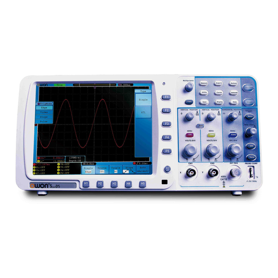
Owon SDS Series Service Manual
Smart digital storage oscilloscopes
Hide thumbs
Also See for SDS Series:
- User manual (98 pages) ,
- Service manual (44 pages) ,
- Quick manual (28 pages)
Subscribe to Our Youtube Channel
Summary of Contents for Owon SDS Series
- Page 1 SDS Series Smart Digital Storage Oscilloscopes Service Manual SDS6062 SDS7102 SDS8102 SDS8202 WWW.OWON.COM.CN...
- Page 2 The information in this manual was correct at the time of printing. However, OWON will continue to improve products and reserves the rights to changes specification at any time without advance notice, for latest information, please refer to our website.
- Page 3 LIMITED WARRANTY & LIMITATION OF LIABILITY SERVICES CENTER...
- Page 4 Table of Contents...
- Page 5 List of Figures List of Tables...
- Page 6 General Safety Summary Operation security Safety Terms and Symbols Specific Warning and Caution Terms that Appear throughout the Manual Warning: Caution: Terms Used on the Product Danger Warning Notice Symbols Used on the Product...
- Page 7 Safety Requirement Only qualified technical personnel are permitted to perform maintenance. Prevent fires and personal injuries. Use professional power wire. Only use the special power wire that is applied to the user state. Connect and cut off in the proper way. Please do not connect or cut off the probe or the tested wires voluntarily when connecting with the power supply.
- Page 8 4800VA: Use only insulated voltage probes, test leads and adapter supplied with the test tool, or indicated by OWON as suitable for the Oscilloscope & Multimeter. Before use, inspect voltage probes, test leads and accessories for mechanical damage and replace when damaged.
- Page 9 Section 1: General Information 1.1 Introduction General Information Installation Test and Calibration Debugging and Calibration Maintenance Replaceable Parts 1.2 Accessories Supplied Standard Accessories: Options: 1.3 Technical Specifications...
- Page 10 Table 1: Specifications (cont.) Performance Characteristics Instruction Acquisition Input Horizontal System...
- Page 11 Table 1: Specifications (cont.) Performance Characteristics Instruction Vertical system Measurement...
- Page 12 Table 1: Specifications (cont.) Performance Characteristics Instruction Communication port...
- Page 13 Table 1: Specifications (cont.) Trigger: Performance Characteristics Instruction...
- Page 14 1.4 General Technical Specifications Table 2: General specifications Display Output of the Probe Compensator Table 2: General Specifications (cont.) Power Mechanical Specifications Interval Period of Adjustment:...
- Page 15 1.5 Declaration of Conformity SDS Series Smart Digital Storage Oscilloscopes...
- Page 16 Section 2: Installation 2.1 Performing the General Inspection 2.1.1 Check whether there is any Damage on it Due to Transportation 2.1.2 Make a Check on Accessories 2.1.3 Make a Check on the Complete Instrument 2.2 Operating Environment Table 3: Environment 2.3 Storage and Transport Be careful:...
- Page 17 2.4 Packaging 2.5 Tagging for Service 2.6 Power Supply Requirement 2.7 Cleaning Requirements Cleaning Warning:...
- Page 18 Section 3: Test and Calibration 3.1 Equipment for Testing 3.2 Test Standard 3.3 Inspection Items and Methods 3.3.1 Appearance and functional inspection A. Appearance inspection B. Functional inspection Autoset 3.3.2 Sweep rate and error inspection...
- Page 19 Figure 1: Figure 2: 3.3.3 Time measurement and error inspection Autoset 3.3.4 Voltage division and error inspection...
- Page 20 Figure 3: 3.3.5 Voltage measurement and error inspection Autoset 3.3.6 Bandwidth inspection Figure 4:...
- Page 21 3.3.7 Transient response inspection Figure 5: Figure 6:...
- Page 22 3.3.8 Vertical movement range inspection Figure 7: 3.3.9 Linear error inspection for vertical movement 3.3.10 Input impedance inspection...
- Page 23 Figure 8: 3.3.11 Drift test 3.3.12 Noise testing 3.3.13 Maximum input voltage testing Figure 9: 3.3.14 Average function testing...
- Page 24 3.3.15 Peak value –testing inspection 3.3.16 Triggering test...
- Page 25 Section 4: Debugging and Calibration 4.1 Brief Introduction 4.2 Tools and Devices 4.3 The Interval Time to Calibration. 4.4 Auto-calibration “Utility” Function Adjust Self Cal 4.5 Attenuation Compensation Capacitance Calibration...
- Page 26 Section 5: Maintenance 5.1 Brief Introduction 5.2 Preparation and Safety Event 5.3 Circuit Diagram Figure 10:...
- Page 28 Figure 11: 5.4 Removal and Installation Procedures Power switch Button Figure 12: Remove the Power switch button Notice for installation: Ground Connection...
- Page 29 Figure 13: Remove the Ground Connection Battery Box Figure 14 Loosen the screws of battery box...
- Page 30 Figure 15: Remove the battery box Notice for installation: Figure 16: Assemble the battery box Rear Panel Notice for installation:...
- Page 32 Figure 17: Remove the screws of rear panel Figure 18: Unsnap the rear panel (1)
- Page 33 Figure 19: Unsnap the rear panel (2) Figure 20: Disconnect the rear panel Battery box Container...
- Page 34 Figure 21: Remove the battery box container Power supply Board...
- Page 35 Figure 22: Cables to power supply board Figure 23: Screws of power supply board Adapter plate...
- Page 36 Figure 24: Disconnect the screen data cable...
- Page 37 Figure 25: Screws and cables of the adapter plate Figure 26: Remove the adapter plate Chassis (including Fan and LCD)
- Page 38 Figure 27: Remove plastic cushion...
- Page 39 Figure 28: Screws of the chassis...
- Page 40 Figure 29: Fan power cable of the chassis Notice for installation:...
- Page 41 Figure 30: Install the chassis (1) Figure 31: Install the chassis (2) Main Board...
- Page 42 Figure 32: Screws secure the main board Notice for installation: Figure 33: Install the main board...
- Page 43 Done. Figure 34: Key board and front panel...
- Page 44 5.6 Examination and Maintenance Figure 35: Troubleshooting procedure (1)
- Page 45 Figure 36: Troubleshooting procedure (2)
- Page 46 Section 6: Replaceable Parts 6.1 Replaceable Parts List Table 4: Replaceable parts list Name Model 6.2 Order Information...


Need help?
Do you have a question about the SDS Series and is the answer not in the manual?
Questions and answers