Advertisement
INTRODUCTION
Use these instructions for the Entero mounting plate when installing an RPMWU/RPMSP-LED01
projector on a 6-axis adjuster (000-101642-01) in a CC50-2301/CC67-3001/CC72-3301 display cube
system. Or when using the mounting plate for direct thrown installations.
TOOLS REQUIRED
• Phillips Screw Driver
INSTRUCTIONS
Installation options for the Entero mounting plate are:
• Front access in a display cube
• Rear access in a display cube
• Direct throw in an alternative installation
FRONT (F) AND REAR (R) ACCESS FOR CUBE INSTALLATIONS
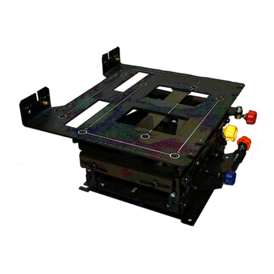
For Entero installations, the 6-axis adjuster comes with the Entero
mounting plate pre-installed for rear access. Rear and front access
refer to the orientation of the adjuster in the cube providing
access to the adjuster controls from the back of the cube or from
the front of the cube. The mounting plate is always installed on
the adjuster with the flange on the side opposite from the adjuster
controls (Figure 1).
Use of Entero Mounting Plate Instruction Sheet
020-100406-02 Rev. 1 (09-2010)
Use of Entero Mounting Plate
Instruction Sheet
Figure 1 Mounting Plate on
6-Axis Adjuster
1 of 4
Advertisement
Table of Contents

Related Manuals for Christie Entero


Summary of Contents for Christie Entero
- Page 1 Use of Entero Mounting Plate Instruction Sheet INTRODUCTION Use these instructions for the Entero mounting plate when installing an RPMWU/RPMSP-LED01 projector on a 6-axis adjuster (000-101642-01) in a CC50-2301/CC67-3001/CC72-3301 display cube system. Or when using the mounting plate for direct thrown installations.
- Page 2 Figure 4 Mounting plate flange - rear access pin holes NOTE: See the CC50/CC67/CC72 Installation Manual (P/N: 020-100248-02) for information about installing the adjuster and mounting plate in the cube and installing the projector. 2 of 4 Use of Entero Mounting Plate Instruction Sheet 020-100406-02 Rev. 1 (09-2010)
- Page 3 2. Loosely install two M5 cap screws on the back of the projector as indicated in Figure 6. Figure 6 Attachment screw location for direct throw Use of Entero Mounting Plate Instruction Sheet 3 of 4 020-100406-02 Rev. 1 (09-2010)
- Page 4 4. Settle the projector on the guide pins and secure to the flange with M5 screws installed in step 2. Figure 8 Mounting plate installed for direct throw 4 of 4 Use of Entero Mounting Plate Instruction Sheet 020-100406-02 Rev. 1 (09-2010)
Need help?
Do you have a question about the Entero and is the answer not in the manual?
Questions and answers