Table of Contents
Advertisement
Quick Links
本書は製品とともに大切に保管してください
Keep this manual carefully.
N8103-91
ディスクアレイコントローラ(内蔵 SAS HDD 用)
ユーザーズガイド
Disk Array Controller (Internal SAS HDD)
User's Guide
製品をご使用になる前に必ず本書をお読みください。
本書は熟読の上、大切に保管してください。
Make sure you read this manual before using the product.
After reading this manual carefully, store it in a safe place.
Advertisement
Chapters
Table of Contents

Related Manuals for NEC N8103-91


Summary of Contents for NEC N8103-91
- Page 1 本書は製品とともに大切に保管してください Keep this manual carefully. N8103-91 ディスクアレイコントローラ(内蔵 SAS HDD 用) ユーザーズガイド Disk Array Controller (Internal SAS HDD) User's Guide 製品をご使用になる前に必ず本書をお読みください。 本書は熟読の上、大切に保管してください。 Make sure you read this manual before using the product. After reading this manual carefully, store it in a safe place.
- Page 2 NEC assumes no liability arising from the use of this product, nor any liability for incidental or consequential damages arising from the use of this manual regardless of Item (4).
- Page 3 い。 Congratulations for your purchase of the Disk Array Controller. The User’s Guide describes how to install and use the N8103-91 Disk Array Controller (Internal SAS HDD) correctly and safely. Read the guide thoroughly before handling it. In addition, refer to this manual when you want to know how to use it or some malfunction occurs.
- Page 4 このユーザーズガイドは、必要なときすぐに参照できるよう、お手元に置いておくようにしてください。 「使用上のご注意」を必ずお読みください。 Keep this User's Guide at hand for quick reference at anytime necessary. Be sure to read this section carefully. 使用上のご注意 ~必ずお読みください~ NOTES ON USE - Always read the Notes - 本製品を安全に正しくご使用になるために必要な情報が記載されています。 The following includes information necessary for proper and safe operation of the product. 安全に関わる表示について...
- Page 5 危険に対する注意・表示は次の3種類の記号を使って表しています。それぞれの記号は次 のような意味を持つものとして定義されています。 Precautions against hazards are presented with the following symbols. The individual symbols are defined as follows: (例) (Example) この記号は危険が発生するおそれがあることを表し ます。 記号の中の絵表示は危険の内容を図案化したも 注意の喚起 のです。 Attention This symbol indicates the presence of a hazard. (感電注意) An image in the symbol illustrates the hazard type. Precaution against electric shock (例) (Example)
-
Page 6: 本書で使用する記号とその内容 Symbols Used In This Manual And Warning Labels
本書で使用する記号とその内容 Symbols Used in This Manual and Warning Labels 注意の喚起 Attentions 特定しない一般的な注意・警告を示します。 Indicates a general notice or warning that cannot be specifically identified. 感電のおそれがあることを示します。 Indicates that improper use may cause an electric shock. 高温による障害を負うおそれがあることを示します。 Indicates that improper use may cause personal injury. 発煙または発火のおそれがあることを示します。... -
Page 7: 安全上のご注意 Safety Indications
NEC does not assume any liability for accidents resulting in injury or death, or for any damages to property that may occur as a result of using the product in such facilities, equipment, or control systems. - Page 8 CAUTION 装置内に水や異物を入れない Keep water or foreign matter away from the server. 装置内に水などの液体、ピンやクリップなどの異物を入れないでください。火災や 感電、故障の原因となります。もし入ってしまったときは、すぐに本体装置の電源 をOFFにして電源コードをACコンセントから抜いてください。分解しないで販売店 または保守サービス会社に連絡してください。 Do not let any form of liquid (water etc.) or foreign matter (e.g., pins or paper clips) enter the server. Failure to follow this warning may cause an electric shock, a fire, or a failure of the server.
- Page 9 <電源・電源コードに関する注意事項> Power Supply and Power Cord Use CAUTION 電源がONのまま取り付け・取り外しをしない Disconnect the power cord(s) before installing or removing the product in/from the server. 本体装置への取り付け・取り外しの際や、周辺機器との接続の際は必ず主電源に接 続している電源コードをACコンセントから抜いてください。 電源コードがACコンセ ントに接続されたまま取り付け・取り外しや接続をすると感電するおそれがありま す。 Make sure to power off the server and disconnect the power cord(s) from a power outlet before installing/removing the product in/from the server, or connecting with the peripheral devices.
- Page 10 破損したケーブルコネクタを使用しない。 ネジ止めなどのロックを確実に行ってください。 Use only interface cables authorized by NEC and locate a proper device and connector before connecting a cable. Using an unauthorized cable or connecting a cable to an improper destination may cause a short circuit, resulting in a fire.
- Page 11 CAUTION 腐食性ガスの存在する環境で使用または保管しない Do not use or store the product in the place where corrosive gases exist. 腐食性ガス(二酸化硫黄、硫化水素、二酸化窒素、塩素、アンモニア、オゾンなど) の存在する環境に設置し、使用しないでください。 また、ほこりや空気中に腐食を促進する成分(塩化ナトリウムや硫黄など)や導電 性の金属などが含まれている環境へも設置しないでください。装置内部のプリント 板が腐食し、故障および発煙・発火の原因となるおそれがあります。もしご使用の 環境で上記の疑いがある場合は、 販売店または保守サービス会社にご相談ください。 Make sure not to locate or use the server in the place where corrosive gases (sulfur dioxide, hydrogen sulfide, nitrogen dioxide, chlorine, ammonia, ozone, etc) exist. Also, do not install it in the environment where the air (or dust) includes components accelerating corrosion (ex.
- Page 12 項> <お手入れに関する注意事 Cleaning and Working wit h the Product WARNING 自分で分解・修理・改造はしない Do not disassemble, repair, or alter the server. 本製品の分解や、修理・改造は絶対にしないでください。装置が正常に動作しなく なるばかりでなく、感電や火災の危険があります。 Never attempt to disassemble, repair, or alter the product on any occasion. Failure to follow this instruction may cause an electric shock or fire as well as malfunctions of the product.
- Page 13 <運用中の注意事項> During Operation CAUTION 雷がなったら触らない Avoid contact with the server during thunderstorms. 雷が鳴りだしたら、本製品内蔵の本体装置には、触れないでください。感電するお それがあります。 Disconnect the power plug from the outlet when a thunderstorm is approaching. If it starts thundering before you disconnect the power plug, do not touch any part of the server containing the product.
-
Page 14: 使用上のご注意 〜装置を正しく動作させるために
使用上のご注意 ~装置を正しく動作させるために~ 本製品を使用するときに注意していただきたいことを次に示します。これらの注意を無視 して、 本製品を使用した場合、 資産(データやその他の装置)が破壊されるおそれがあります ので必ずお守りください。 本製品は Express5800 シリーズに Serial Attached SCSI(SAS)機器を接続する ためのディスクアレイコントローラです。他の目的では使用しないでください。 本製品は大変デリケートな電子装置です。本製品を取り扱う前に、本体装置の金 属フレーム部分などに触れて身体の静電気を逃がしてください。 本製品の取り扱い は端の部分を持ち、 表面の部品やコネクタと接続する部分には触れないようにして ください。また、本製品を落としたり、ぶつけたりしないでください。 本製品には、同一規格のハードディスクドライブ(以降「HDD」と呼ぶ)を接続 してください。 本製品に接続可能な本体装置、増設用 HDD ケージ、HDD については、お買い求 めの販売店にお問い合わせください。 本製品は、 他の PCI ボード (ディスクアレイコントローラ、 ミラーリングボード、 SCSI コントローラ等)の混在使用を制限している場合があります。本製品を他の PCI ボードと混在してご使用になる場合は、 混在が可能かどうかお買い求めの販売 店にご確認ください。 電波障害自主規制について この装置は、情報処理装置等電波障害自主規制協議会(VCCI)の基準に基づくクラス... -
Page 15: 本書について This Manual
xiii 本書について This Manual 本書は、Windows などのオペレーティングシステムやキーボード、マウスといった一般的 な入出力装置などの基本的な取り扱いについて十分な知識を持ったユーザを対象として記 載されています。 The guide is intended for persons who are familiar with operating systems including Windows and fundamental operations of general-purpose I/O devices including the keyboard and mouse. <本書の記号について> Text Conventions 本書の中には安全に関わる注意記号の他に次の3種類の記号を使用しています。それぞれ の記号は次のような意味をもつものとして定義されています。 The following conventions are used throughout this User's Guide. For safety symbols, see "SAFETY INDICATIONS"... -
Page 16: 第三者への譲渡について Transfer To Third Party
For details on data erasure, ask your sales representative. NEC assumes no liability for data leakage if the product is transferred to third party without erasing the data. -
Page 17: 廃棄について Disposal
The device failure due to shock or thermal changes, as well as operator's misconduct, may cause loss of data. To avoid loss of data, NEC recommends that you should make a back-up copy of your valuable data on a regular basis. -
Page 18: 本書で使用する略称 Abbreviations
略 称 Formal title Abbreviation N8103-91 ディスクアレイコントローラ 本書 (内蔵 SAS HDD 用)ユーザーズガイド this manual N8103-91 Disk Array Controller (Internal SAS HDD) User’s Guide N8103-91 ディスクアレイコントローラ 本製品またはディスクアレイコント (内蔵 SAS HDD 用) ローラ N8103-91 Disk Array Controller (Internal SAS HDD) disk array controller or card N8103-94 増設バッテリ... -
Page 19: Table Of Contents
xvii 目 次 まえがき Preface ........................i 使用上のご注意 〜必ずお読みください〜 NOTES ON USE - Always read the Notes -ii 本書で使用する記号とその内容 Symbols Used in This Manual and Warning Labels....iv 安全上のご注意 Safety Indications..................v 使用上のご注意 〜装置を正しく動作させるために〜............xii 本書について This Manual....................xiii 梱包箱の中身について In the Package................. xiii 第三者への譲渡について... - Page 20 xviii 第 3 章 本製品の機能について..................21 1.リビルド ..........................21 1-1.マニュアルリビルド(手動リビルド) .................21 1-2.オートリビルド(自動リビルド)..................21 2.パトロールリード ........................23 3.整合性チェック........................24 4.バックグラウンドイニシャライズ...................25 5.リコンストラクション......................26 5-1. Removed physical drive ....................26 5-2. Migration only ........................26 5-3. Migration with addition....................26 第 4 章 バーチャルディスクの作成..................28 1.WebBIOS を使用する前に......................28 1-1.サポート機能 ........................28 1-2.バーチャルドライブ作成時の注意事項................29 2. WebBIOS の起動とメニュー....................30 2-1.
-
Page 21: 第 1 章 概要
第 1 章 概要 本製品を初めてお使いになる場合は、この章からお読みください。 ここでは、本製品の運用上必ずお守りしていただきたい事項、ならびに、本製品の特徴と ハードウェアのセットアップについて説明します。 1.運用上のご注意 ~必ずお守りください~ 本製品を安全に運用していただくため、以下の注意事項をお守りください。 1-1. MSM のインストールについて 本製品をオペレーティングシステム(以降「OS」と呼ぶ)上から管理することができる管理 ユーティリティ MegaRAID Storage Manager (以降「MSM」と呼ぶ)を必ずインストール してください。MSM をインストールすることにより、 アレイシステム上発生したイベントや異常がイベントログに登録され、システム の障害解決や診断に有効活用できます。 ESMPRO を使って MSM のイベント情報を監視することが可能です。 マニュアルリビルド/整合性チェックの実行が可能になります。 MSM のインストール方法は、本体装置添付の EXPRESSBUILDER に収められている 「Express5800 シリーズ MegaRAID Storage Manager ユーザーズガイド」をご覧くだ さい。... -
Page 22: 1-2.整合性チェックによる予防保守
1-2.整合性チェックによる予防保守 ハードディスクドライブ(以降「HDD」と呼ぶ)の後発不良に対する予防保守として、整合 性チェックを定期的に実施することをお勧めします。 この機能により、HDD の後発不良を 早期に発見し修復することができます。 整合性チェックの詳しい機能については、 『第 3 章本製品の機能について』 をご覧ください。 実施の間隔は週に 1 度実施されることを推奨していますが、 お客さまの運用状況に合わせ、 少なくとも月に 1 度は実施されることをお勧めしています。 整合性チェックを実施するためには、 MSM のインストールが必要になりま す。... - Page 23 2.仕様 項 目 仕 様 備 考 SAS コネクタ数 内部 2 チャネル 1 チャネルに 4 ポート キャッシュ容量 256MB PCI バス PCI Express 1.0A 準拠 PCI コネクタ PCI Express (x8) 66MHz 最大 PCI バス転送レート 2,5Gigabits/lane デバイスインターフェース SAS 対応 最大データ転送レート 300MB/sec RAID レベル RAID1 のスパン,RAID5 の...
-
Page 24: 本製品の特徴
3.本製品の特徴 本製品は、SAS 対応の I/F コネクタが 2 チャネル(1 チャネルに 4 ポート)搭載されてい ます。データ転送速度は、1 ポートあたり最大 300MB/秒であり、高パフォーマンスを実 現しています。 さらに、N8103-94 増設バッテリ (以降「増設バッテリ」と呼ぶ)と接続することで、アク セス性能がより向上する「Write Back」モードでの運用が可能になります。 本製品の特徴 最大 300MB/秒のデータ転送 256MB DDR-Ⅱ メモリを搭載 1 ボードあたり最大 8 台の SAS HDD を接続可能(1 チャネル当たり 4 台) RAID レベル 0, 1, 5, RAID1 のスパン, RAID5 のスパン をサポート 増設バッテリを接続することにより、... -
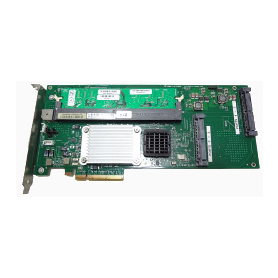
Page 25: 各部の名称と機能
4.各部の名称と機能 本製品の各部の名称を以下に説明いたします。 (本製品表面) (本製品裏面) - Page 26 チャネル 1(Port 0〜3) SAS デバイス機器を接続するためのコネクタです。 チャネル 2(Port 4〜7) SAS デバイス機器を接続するためのコネクタです。 HW ラベル 本製品の管理レビジョンを表示しているラベルです。 メモリ用コネクタ メモリまたは N8103-94 増設バッテリを接続するためのコネクタです。 N コードラベル 本製品のNコードを表示しています。 N8103-91 PCI コネクタ(PCI Express 対応) 本体装置の PCI スロット(PCI Express)に接続するコネクタです。...
-
Page 27: ハードウェアのセットアップ
5.ハードウェアのセットアップ 次の手順に従って、本製品を本体装置に取り付けてください。 作業の前に本体装置のユーザーズガイドも必ずご覧になってください。 作業 フローは本体装置や装置構成によって異なります。 作業開始前に本体装置の 種類および装置構成を確認して正しいフローを実施してください。 セットアップ開始 セットアップの準備 増設バッテリの取り付け(*) 本製品の取り付け SAS ケーブルの接続 セットアップ終了 (*)増設バッテリを使用しない場合は、作業はありません。... -
Page 28: 5-1.セットアップの準備
5-1.セットアップの準備 セットアップを行う前に、以下の注意事項をご覧ください。 本製品は、本体装置1台に対して1枚のみ実装可能です。複数枚の実装は できません。 PCI スロット(PCI Express)には、本体装置により実装制限がある場合 があります。取り付ける前に本体装置のユーザーズガイドを確認してく ださい。 本製品に接続するHDD は、同一規格のHDD を使用してください。本製 品に接続可能なHDD については、お買い求めの販売店にご確認くださ い。 本製品は、他のPCI ボード(ディスクアレイコントローラ、ミラーリング ボード、SCSI コントローラ等)の混在使用を制限している場合がありま す。本製品を他のPCI ボードと混在してご使用になる場合は、混在が可 能かどうかお買い求めの販売店にご確認ください。 すべてのアプリケーションを終了し、OS のシャットダウン処理を行います。 POWER スイッチを押して本体装置の電源をOFFにします。 本体装置の電源ユニットに接続している全ての電源コードをコンセントから抜き ます。 本体装置のユーザーズガイドの手順に従い、本体装置のサイドカバー等を外しま す。 本体装置サイドカバー等の取り付け/取り外し手順は、本体装置のユーザー ズガイドをご覧ください。... -
Page 29: 5-2.増設バッテリの取り付け
5-2.増設バッテリの取り付け N8103-94 増設バッテリを使用する場合は、本製品に搭載されているメモリを増設バッテ リに交換する必要があります。 メモリを固定しているつめを開いてください。 メモリを取り外します。 増設バッテリをスロットにしっかり差し込みます。 手順 1 で開いたつめを閉じ、増設バッテリを固定します。 メモリ(256MB DIMM-Ⅱ) N8103-94 増設バッテリ 増設バッテリの詳しい取り付け方法については、 「N8103-94 増設バッテリ ユーザーズガイド」をご覧ください。 増設バッテリから本製品添付のメモリに取り替える時も同じ手順です。... -
Page 30: 5-3.本製品の取り付け
5-3.本製品の取り付け 本製品を取り付ける PCI スロット(PCI Express)の位置を確認し、対応する増 設スロットカバーを取り外します。 取り外した増設スロットカバーは大切に保管してください。外したネジ は、本製品の取り付けに使用しますので、なくさないでください。 本製品は、PCI ホットプラグ機能には対応していません。本製品を抜き 差しする場合は、必ず本体装置の電源をOFF にして、電源コードをコン セントから抜いてください。 PCI スロットには、本体装置により実装制限がある場合があります。取り 付ける前に本体装置のユーザーズガイドをご覧ください。 本製品を PCI スロット(PCI Express)にしっかりと差し込み、固定します。ネ ジで固定する場合は、増設スロットカバーを取り外した時のネジを使用して固定 します。 本製品 (ディスクアレイコントローラ) ネジ 取り付け例.ラックマウントモデルの場合... - Page 31 本製品 (ディスクアレイコントローラ) ネジ 取り付け例.タワーモデルの場合 本製品がPCI スロット (PCI Express) にうまく取り付けられない場合は、 一旦本製品を取り外して、再度取り付けなおしてください。過度の力を 加えると破損するおそれがありますので注意してください。...
-
Page 32: Sas ケーブルの接続
5-4. SAS ケーブルの接続 SAS ケーブルを本製品の SAS コネクタに接続します。以下の図および接続表を参照して 接続してください。本体装置への接続については本体装置のユーザーズガイドをご覧くだ さい。ケーブルが接続しづらい場合は、一旦本製品を PCI スロット(PCI Express)から抜 いて接続してください。 SAS ケーブル Port 4 - 7 SAS ケーブル Port 0 - 3 SAS コネクタ Port 4 - 7 SAS コネクタ Port 0 - 3 取り付け例.ラックマウントモデルの場合 ... - Page 33 SAS コネクタ SAS コネクタ Port 4 - 7 Port 0 - 3 SAS ケーブル Port 4 - 7 SAS ケーブル Port 0 - 3 取り付け例.タワーモデルの場合 ポート番号は、本体装置におけるHDDの物理的な位置により、一通りに定 められています。 本製品と本体装置にSASケーブルをつなぐ際は、 必ずポー ト番号に対応したコネクタを確認し、 ケーブルを差し込んでください。 間違 えて差し込むと故障の原因になります。本体装置のポート番号については、 本体装置のユーザーズガイドをご覧ください。...
-
Page 34: 第 2 章 Raid について
第 2 章 RAID について ここでは、本製品がサポートしている RAID 機能について説明します。 1. RAID の概要 1-1. RAID(Redundant Array of Inexpensive Disks)とは 直訳すると低価格ディスクの冗長配列となり、ハードディスクドライブ(以降「HDD」と呼 ぶ)を複数まとめて扱う技術のことを意味します。 つまり RAID とは複数の HDD を 1 つのアレイ(ディスクグループ)として構成し、これらを 効率よく運用することです。 これにより単体の大容量 HDD より高いパフォーマンスを得る ことができます。 本製品では、 1つのディスクグループを複数の論理ドライブ(バーチャルディスク)に分けて 設定することができます(最大 40 個)。これらのバーチャルディスクは、ホストコンピュー タからそれぞれ 1 つの HDD として認識されます。ホストコンピュータからのアクセスは、 ディスクグループを構成している複数の... -
Page 35: 1-3.ディスクグループ(Disk Group)
各RAID レベルの詳細は、本章「2.RAID レベル」を参照してください。 1-3.ディスクグループ(Disk Group) ディスクグループは複数の HDD をグループ化したものを表します。本製品の設定可能な ディスクグループの数は、HDD を 8 台実装した場合で最大 8 個になります。 次の図は本製品に HDD を 3 台接続し、3 台で1つのディスクグループ(DG)を作成した構 成例です。 ディスクアレイコントローラ DG0 容量 108GB ディスク 1 ディスク 2 ディスク 3 (36GB) (36GB) (36GB) -
Page 36: 1-4.バーチャルディスク(Virtual Disk)
1-4.バーチャルディスク(Virtual Disk) バーチャルディスクは作成したディスクグループ内に、論理ドライブとして設定したもの を表し、 OS からは物理ドライブとして認識されます。 本製品の設定可能なバーチャルディ スクの数は、最大 40 個になります。 次の図は本製品に HDD を 3 台接続し、3 台で1つのディスクグループ(DG)を作成し、そ の DG に RAID5 のバーチャルディスク(VD)を2つ設定した構成例です。 ディスクアレイコントローラ DG0 容量 108GB VD0 (RAID5) VD0-1 VD0-2 VD0-3 容量 40GB 20GB 20GB 20GB VD1-1 VD1-2 VD1-3 VD1 (RAID5) 16GB 16GB 16GB... -
Page 37: 1-7.ホットスペアディスク(Hot Spare)
1-7.ホットスペアディスク(Hot Spare) ホットスペアディスクとは、冗長性のある RAID レベルで構成されたロジカルドライブ配 下の HDD に障害が発生した場合に、 代わりに使用できるように用意された予備の HDD で す。HDD の障害を検出すると、障害を検出した HDD を切り離し(オフライン)、ホットス ペアディスクを使用してリビルドを実行します。 ホットスペアディスクを使用したリビルド 「スタンバイリビルド」 について は『第3章本製品の機能について』を参照してください。... -
Page 38: Raid レベル
2. RAID レベル 本製品がサポートしている RAID レベルについて詳細な説明をします。 2-1. RAID レベルの特徴 各 RAID レベルの特徴は下表の通りです。 レベル 機 能 冗長性 特 徴 ストライピング なし データ読み書きが最も高速 RAID0 容量が最大 容量=HDD1 台の容量×HDD 台数 ミラーリング あり HDD が 2 台必要 RAID1 容量=HDD1 台の容量 データおよび冗長データ あり HDD が 3 台以上必要 RAID5 のストライピング... -
Page 39: Raid1」について
2-3.「RAID1」について 1 つの HDD に対してもう 1 つの HDD へ同じデータを記録する方式です。 この方式を 「ミ ラーリング」と呼びます。 1 台の HDD にデータを記録するとき同時に別の HDD に同じデータが記録されます。 一方 の HDD が故障したときに同じ内容が記録されているもう一方の HDD を代わりとして使 用することができるため、システムをダウンすることなく運用できます。 アレイコントローラ Disk 1 Disk 2 ストライプ 1 ストライプ 1 ストライプ 2 ストライプ 2 2-4.「RAID5」について RAID0 と同様に、データを各 HDD へ「ストライピング」方式で分散して記録しますが、 そのときパリティ(冗長データ)も各... -
Page 40: Raid1 のスパン」について
2-5.「RAID1 のスパン」について データを 2 つの HDD へ「ミラーリング」方式で分散し、さらにそれらのミラーを「スト ライピング」方式で記録しますので、RAID0 の高いディスクアクセス性能と、RAID1 の 高信頼性を同時に実現することができます。 アレイコントローラ Disk 1 Disk 2 Disk 3 Disk 4 ストライプ 1 ストライプ 1 ストライプ 2 ストライプ 2 ストライプ 3 ストライプ 3 ストライプ 4 ストライプ 4 ストライプ 5 ストライプ 5 ストライプ... -
Page 41: 第 3 章 本製品の機能について
第 3 章 本製品の機能について 本製品が持つ機能を説明します。 1.リビルド リビルド(Rebuild)は、ハードディスクドライブ(以降「HDD」と呼ぶ)に故障が発生した場 合に、故障した HDD のデータを復旧させる機能です。 『RAID1』や『RAID5』など、冗長 性のあるバーチャルディスクに対して実行することができます。 1-1.マニュアルリビルド(手動リビルド) 本製品の管理ユーティリティ MegaRAID Storage Manager (以降「MSM」と呼ぶ)を使用 し、手動で実施するリビルドです。HDD を選択してリビルドを実行することができます。 詳しい操作方法については、本体装置添付の EXPRESSBUILDER に収められている 「Express5800 シリーズ MegaRAID Storage Manager ユーザーズガイド」をご覧くだ さい。 1-2.オートリビルド(自動リビルド) MSM などのユーティリティを使用せず、自動的にリビルドを実行させる機能です。 オートリビルドには、以下の 2 種類の方法があります。 スタンバイリビルド ホットスペアディスクを用いて自動的にリビルドを行う機能です。ホットスペア ディスクが設定されている構成では、バーチャルディスクに割り当てられている HDD に故障が生じたときに、自動的にリビルドが実行されます。 ホットスワップリビルド... - Page 42 リビルドを実行する場合は、以下の点に注意してください。 リビルドに使用するHDD は、故障したHDD と同一容量、同一回転数、 同一規格のものを使用してください。 リビルド中は負荷がかかるため、処理速度は低下します。 リビルド中は、本体装置のシャットダウンやリブートを実施しないでく ださい。万が一、停電などの不慮な事故でシャットダウンしてしまった 場合、速やかに電源の再投入を行ってください。自動的にリビルドが再 開されます。 故障したHDD を抜いてから新しいHDD を実装するまでに、90秒以上の 間隔をあけてください。 ホットスワップリビルドが動作しない場合は、マニュアルリビルドを実 行してください。 ホットスペアディスクは、パーティションのあるハードディスクドライ ブおよび他アレイで使用していたハードディスクドライブを指定できま せん。この場合、新品のハードディスクドライブか、フォーマット済み のハードディスクドライブを使用してください。...
-
Page 43: パトロールリード
2.パトロールリード パトロールリード(Patrol Read)は、HDD の全領域にリード&ベリファイ試験を実施する機 能です。パトロールリードは、バーチャルディスクやホットスペアに割り当てられている すべての HDD に対して実行することができます。 パトロールリードにより、HDD の後発不良を検出・修復することができます。 冗長性のあるバーチャルディスクを構成する HDD やホットスペアディスクに割り当てら れた HDD の場合は、実行中に検出したエラーセクタを修復することができます。 パトロールリードを実行する場合は、以下の点に注意してください。 パトロールリードは、工場出荷時は「Disable」に設定されています。 メディアパトロールを実施するためにはMSMのインストールが必要で す。 パトロールリード実行中にシステムの再起動を行うと最初 (HDDの先頭) からパトロールリードをやり直します。 詳しい操作方法については、本体装置添付のEXPRESSBUILDERに収め られている「Express5800 シリーズ MegaRAID Storage Manager ユーザーズガイド」をご覧ください。... -
Page 44: 整合性チェック
3.整合性チェック 整合性チェック(Check Consistency)は、バーチャルドライブの整合性をチェックするため の機能です。 『RAID1』や『RAID5』など、冗長性のあるバーチャルドライブに対して実行 することができます。 整合性チェックは、WebBIOS や MSM から実施することができます。 整合性チェックは整合性をチェックするだけでなく、実行中に検出したエラーセクタを修 復することができるため、予防保守として使用できます。 整合性チェックを実行する場合は、以下の点に注意してください。 整合性チェック中は負荷がかかるため、処理速度は低下します。 整合性チェック実行中にシステムの再起動を行うと途中から再開しま す。 詳しい操作方法については、本体装置添付のEXPRESSBUILDERに収め られている「Express5800 シリーズ MegaRAID Storage Manager ユーザーズガイド」をご覧ください。... -
Page 45: バックグラウンドイニシャライズ
4.バックグラウンドイニシャライズ 5 台以上の HDD で構成されたディスクグループに RAID5 のバーチャルディスクを作成し た場合、自動的にバックグラウンドイニシャライズ(Background Initialize)が実施されます。 バックグラウンドイニシャライズ機能は、初期化されていない領域に対してバックグラウ ンドでパリティ生成処理を行う機能であり、整合性チェックと同等の処理を行います。 ただし、以下の場合はバックグラウンドイニシャライズが実施されません。 バックグラウンドイニシャライズが実施される前にフルイニシャライズ(Full Initialize)(*)を実施し、正常に完了している場合 バックグラウンドイニシャライズが実施される前に整合性チェックを実施し、正 常に完了している場合 バックグラウンドイニシャライズを実施される前にリビルドを実施し、正常に完 了している場合 バーチャルディスク作成時に、 「Disable BGI」の設定を「Yes」に設定した場合 (*)フルイニシャライズは、バーチャルディスクの領域全体を「0」でクリアする機能です。 また、一旦バックグラウンドイニシャライズが完了しているバーチャルディスクに対して 以下の操作を行った場合は、再度バックグラウンドイニシャライズが実施されます。 バーチャルディスクが縮退状態(Degraded)やオフライン状態(Offline)の場合に、 オ フラインの HDD に Make Online を実施し、バーチャルディスクが Optimal になっ た場合 ディスクアレイコントローラを保守部品などに交換した場合 既存のバーチャルディスクにリコンストラクションを実施し、HDD5 台以上の RAID5 構成に変更した場合 バックグラウンドイニシャライズを実行する場合は、... -
Page 46: リコンストラクション
5.リコンストラクション リコンストラクション(Reconstruction)機能は、既存のバーチャルディスクの RAID レベル や構成を変更する機能です。リコンストラクション機能には以下の3通りの機能がありま すが、本製品では Migration with addition のみをサポートしています。 5-1. Removed physical drive 本製品では未サポートです。 5-2. Migration only 本製品では未サポートです。 5-3. Migration with addition 既存のバーチャルディスクに HDD を追加する機能です。MSM 上では、 「Add Drive」と表 示されます。本機能の実行パターンは以下の通りです。 (α:追加する HDD の数) 実行前 実行後 特 徴 RAID レベル HDD 数 RAID レベル... - Page 47 リコンストラクションを実行する場合は、以下の点に注意してください。 リコンストラクション実行前に、必ずデータのバックアップと整合性 チェックを実施してください。 1つのディスクグループに複数のバーチャルディスクを作成している構 成には、リコンストラクションは実施できません。 リコンストラクション中は負荷がかかるため、処理速度は低下します。 縮退状態(Degraded)のバーチャルディスクには実行できません。リビル ドを実行し、バーチャルディスクを復旧した後で実行してください。 リコンストラクション中は、本体装置のシャットダウンやリブートを実 施しないでください。万が一、停電等の不慮の事故でシャットダウンを してしまった場合は、速やかに電源を再投入してください。再起動後、 自動的に再開されます。 構成によっては、リコンストラクションが完了後に、自動的にバックグ ラウンドイニシャライズが実行される場合があります。 例) RAID5 のバーチャルディスクの Migration with addition 以下は、36GB HDD×3 台で構成された RAID5 のバーチャルディスクに、36GB HDD を 1 台追加する場合の例です。 バーチャルディスク(RAID5) 【実行前】 容量 = 72GB 36GB 36GB 36GB 36GB Migration with addition 実行 バーチャルディスク(RAID5)...
-
Page 48: 第 4 章 バーチャルディスクの作成
第 4 章 バーチャルディスクの作成 ここでは本製品のコンフィグレーションユーティリティ 「WebBIOS」 について説明します。 1.WebBIOS を使用する前に 「WebBIOS」を使用する前に、サポート機能および注意事項をご覧ください。 1-1.サポート機能 ハードディスクドライブ(以降「HDD」と呼ぶ)のモデル名/容量の情報表示 HDD の割り当て状態表示 バーチャルディスクの作成 RAID レベルの設定 Stripe Block サイズの設定 Read Policy/Write Policy/IO Policy の設定 バーチャルディスクの設定情報・ステータスの表示 バーチャルディスクの削除 コンフィグレーションのクリア イニシャライズの実行 整合性チェックの実行 マニュアルリビルドの実行 リコンストラクションの実行... -
Page 49: 1-2.バーチャルドライブ作成時の注意事項
1-2.バーチャルドライブ作成時の注意事項 1) DG を構成する HDD は同一容量および同一回転のものを使用してください。 2) VD を構築した後、必ず Consistency Check を実施してください。 3) 本製品配下の VD に OS をインストールする際は、OS インストール用の VD のみを作 成してください。 4) 一部の装置でマウスが使用できません。その場合、キーボードの TAB キーで画面上に 表示されているカーソルを移動し Enter キーで決定してください。 Configuration Wizard で ディスクまたはディスクグループを選択する場合はShift キーを押しながら上下のカーソル キーでディスクを選択してください。 5) WebBIOS は本体装置でサポートしている DianaScope のリモートコンソール機能では 動作しません。... -
Page 50: Webbios の起動とメニュー
2. WebBIOS の起動とメニュー 2-1. WebBIOS の起動 1)本体装置の電源投入後、 次に示す画面が表示された時に、 [Esc]キーを押してください。 2)POST 画面が表示されたら<Ctrl>+<H>キーを押して WebBIOS を起動します。 【POST 画面イメージ(バーチャルディスク未設定時)】 LSI MegaRAID SAS - MFI BIOS Version XXXX (Build MMM DD, YYYY) Copyright (c) 2005 LSI Logic Corporation HA - X (Bus X Dev X) MegaRAID SAS 8408E X.X.X - XXXX FW package: X.X.X - XXXX 0 Logical Drive(s) found on the host adapter. -
Page 51: Main Menu
2-2. Main Menu WebBIOS を起動すると最初に表示される[Adapter Selection]画面です。WebBIOS を用い て操作を実施するコントローラを選択し、”Start”をクリックしてください。 Adapter Selection Adapter No. Bus No Device No Type Firmware Version MegaRAID SAS 8408E X.XX.XX - XXXX MegaRAID SAS 8480E X.XX.XX - XXXX Start... - Page 52 [Adapter Selection]を実行すると WebBIOS トップ画面が表示されます。 MegaRAID BIOS Configuration Utility Virtual Configuration Physical Drives WebBIOS Enclosure XXX PD 0: UNCONF GOOD: XXXX MB: XXXX XXXX Adapter Properties PD 1: UNCONF GOOD: XXXX MB: XXXX XXXX Scan Devices PD 2: UNCONF GOOD: XXXX MB: XXXX XXXX Virtual Disks Physical Drives Configuration Wizard...
-
Page 53: Adapter Properties
2-3. Adapter Properties WebBIOS トップ画面にて[Adapter Properties]をクリックすると、 本製品の設定情報を表示 することができます。 MegaRAID BIOS Configuration Utility Adapter Information MegaRAID SAS 8408E Firmware Version X.XX.XX-XXXX WebBIOS Version X.XX-XXX Sub Vendor ID Sub Device ID 0x1000 0x1001 Host Interface Port Count PCIE NVRAM Size Memory Size 32 KB 256 MB Firmware Time... - Page 54 設定情報画面にて[Next]をクリックすると、本製品の詳細設定を表示することができます。 MegaRAID BIOS Configuration Utility Adapter Properties Properties Battery Back Up Coercion Mode Present None Set Factory Defaults PDF Interval Cluster Mode Alarm Control Disabled Disabled Rebuild Rate Int Throttle Cnt Patrol Read Rate Int Throttle Time BGI Rate Cache Flush Interval CC Rate...
- Page 55 初期設定および、設定値説明 項目 設定値 説明 変更可否 備考 バッテリ(N8103-94)の Battery Backup プロパティ画面を表示します。 Present ・バッテリ搭載時 : Present None ・バッテリ未搭載時: None Set Factory Defaults 本製品の設定を工場出荷時の状 可 態に戻します。 Disabled Cluster Mode 不可 Rebuild Rate 奨励設定値: 30 可 Patrol Read Rate 奨励設定値: 30 可 奨励設定値: 30 可...
- Page 56 N8103-94 を搭載している際には、”Battery Backup”のステータスが”Present”と表示されま す。[Present]をクリックすると、下記のバッテリステータス画面が表示されます。 MegaRAID BIOS Configuration Utility Battery Module Battery Type: iBBU Design Info Voltage: XXXXX mV Mfg Name: LSIC10000B Current: Mfg Date: MM/DD/YYYY Temperature: 31 deg centigrade Serial No: XXXX Status: Design Capacity: 880mAh Design Voltage: 4800mV Device Name: 5806-2 Device Chemistry: NiMH...
-
Page 57: Scan Devices
2-4. Scan Devices WebBIOS トップ画面にて[Scan Devices]をクリックすると、 本製品に接続されている HDD を再認識します。この機能は WebBIOS 起動後に新たな HDD を接続した際に有効です。 新たに接続したHDDに他のコンフィグレーション情報が保存されている場 合、下記の[Foreign Configuration]画面が表示されます。そのまま新規HDD として使用する場合は、”ClearForeignCfg”をクリックしてください。 新たに接続したHDD内のコンフィグレーション情報がクリアされます。 MegaRAID BIOS Configuration Utility Foreign Configuration 1 Foreign Config(s) Found. Want to Import? Select GUID GuidPreview ClearForeignCfg Cancel... -
Page 58: Virtual Disks
2-5. Virtual Disks WebBIOS トップ画面にて[Virtual Disks]をクリックすると、 すでに構成されている VD に対 する操作画面が表示されます。 MegaRAID BIOS Configuration Utility Virtual Disks VD X: RAID X: XXXXXX MB: Optimal Fast Initialize Slow Initialize Check Consistency Properties Set Boot Drive (Current = 0) Reset Home Back VDが存在しない場合は、画面右上の欄にVDが表示されません。 本操作画 面はVDが存在するときに使用してください。... -
Page 59: Physical Drives
2-6. Physical Drives WebBIOS トップ画面にて[Physical Disks]をクリックすると、本製品に接続されている Physical Drive(HDD)に対する操作画面が表示されます。 MegaRAID BIOS Configuration Utility Physical Disks Enclosure XXX PD 0: UNCONF GOOD: XXXXXX MB: XXXX XXXXX PD 1: UNCONF GOOD: XXXXXX MB: XXXX XXXXX PD 2: UNCONF GOOD: XXXXXX MB: XXXX XXXXX Rebuild Properties Reset... -
Page 60: Configuration Wizard
2-7. Configuration Wizard 本製品に接続した HDD を用いて RAID を構築する機能です。本機能については次項”バー チャルディスクの構築”にて説明します。 2-8. Adapter Selection 本体装置に本製品を複数枚実装した際に、 各アダプターの設定を行うために、 WebBIOS に てコントロールするアダプターを変更する必要があります。WebBIOS トップ画面より [Adapter Selection]をクリックすると、WebBIOS 起動時に表示される[Adapter Selection] 画面が再度表示されます。 2-9. Physical View / Logical View 本製品を用いて VD を構築している場合、WebBIOS トップ画面にディスクグループ(DG) が表示されます。[Physical View]をクリックすると、DG を構築している HDD の情報が表 示されます。[Logical View]をクリックすると、DG 内で構築されている VD が表示されま す。... -
Page 61: Exit
2-11. Exit WebBIOS トップ画面より[Exit]をクリックすると、 WebBIOS を終了するための確認画面が 表示されます。WebBIOS を終了する際は、下記画面にて[Yes]をクリックしてください。 Exit Configuration Exit Application WebBIOS が終了すると、下記の画面が表示されます。本体装置を再起動してください。 Reset Page Please Reboot your System... -
Page 62: バーチャルディスクの構築
3. バーチャルディスクの構築 ここでは WebBIOS を用いて、VD(バーチャルディスク)を構築する手順を説明します。 3-1.Configuration Wizard WebBIOS を起動し、トップ画面より[Configuration Wizard]をクリックすると、下記の画面 が表示されます。該当する操作を選択し、画面右下の[Next]をクリックしてください。 MegaRAID BIOS Configuration Utility Configuration Wizard Configuration Wizard guides you through the steps for configuration the MegaRAID System easily and efficiently. The steps are as follows: 1. Array definitions Group physical drives into arrays. - Page 63 [New Configuration]または[Add Configuration]を選択した場合、下記の画面が表示されます。 MegaRAID BIOS Configuration Utility Configuration Wizard Wizard can be define the most efficient configuration for your system (Auto Configuration), Or if you are an experienced user, Wizard can take you through the steps (Custom Configuration) Custom Configuration: Allows you to define all aspects of the configuration, disk groups, virtual disks, and their parameters.
- Page 64 複数台の PD(Physical Drive)をひとまとめの DG(Disk Groups)として定義します。 MegaRAID BIOS Configuration Utility ConfigWizard - DG Definition Disk Group Definition: To add drives to a Disk Group, hold Control key while selecting Unconf Good drives and click on Accept DG, Drive addition can be undone by selecting the Reclaim button.
- Page 65 ① DG を構成する Physical Drive(HDD)を<Ctrl>キーを押しながらクリックすることで、 複 数台選択します。 Physical Drives Disk Groups Enclosure XXX PD 0: UNCONF GOOD: XXXXX MB: PD 1: UNCONF GOOD: XXXXX MB: PD 2: UNCONF GOOD: XXXXX MB: Reset Accept DG Reclaim ② 選択完了後、画面右下の[Accept DG]をクリックします。 Physical Drives Disk Groups Enclosure XXX PD 0: UNCONF GOOD: XXXXX MB:...
- Page 66 前画面の操作で作成した DG 内に VD を構築します。DG 確定後、VD 定義画面が表示され ます。 画面右側の Configuration 欄内には構築した DG と、 DG 内に構築可能な VD の RAID レベルおよび最大サイズが表示されています。 MegaRAID BIOS Configuration Utility ConfigWizard – VD Definition Virtual Disk 0 Configuration RAID Level RAID 5 DG 0 :R0 = XXXXX MB, R5 = XXXXX MB Strip Size 64 KB Access Policy...
- Page 67 例として、RAID 5 サイズ YYYYY MB の VD を構築します。 ① 画面左側 Virtual Disk 欄へ必要なパラメータを入力します。 。 ② “Select Size”欄へ RAID 5 にて構築できる最大サイズ YYYYY を入力します。 ③ 画面中央下、[Accept]をクリックします。 Virtual Disk 0 Configuration RAID Level DG 0 :R0 = XXXXX MB, R5 = YYYYY MB RAID 5 Strip Size 64 KB...
- Page 68 ④ DG 0 内に VD 0 が構築され、以下の画面が表示されます。 MegaRAID BIOS Configuration Utility ConfigWizard - DG Definition Disk Group Definition: To add drives to a Disk Group, hold Control key while selecting Unconf Good drives and click on Accept DG, Drive addition can be undone by selecting the Reclaim button.
- Page 69 ⑨ WebBIOS トップ画面が表示され、画面右下に構築した VD が表示されます。 MegaRAID BIOS Configuration Utility Virtual Configuration Physical Drives WebBIOS Enclosure XXX Adapter Properties PD 0: A 0: ONLINE: XXXX MB: XXXX XXXX PD 1: A 0: ONLINE: XXXX MB: XXXX XXXX Scan Devices PD 2: A 0: ONLINE: XXXX MB: XXXX XXXX Virtual Disks Physical Drives Configuration Wizard...
-
Page 70: Configure Span
3-2. Configure SPAN 例として、4 台の HDD を使用して RAID1 のスパンを構築する手順を下記に説明します。 ① WebBIOS トップ画面より[Configuration Wizard]をクリックして、 Wizard を起動します。 MegaRAID BIOS Configuration Utility ConfigWizard - DG Definition Disk Group Definition: To add drives to a Disk Group, hold Control key while selecting Unconf Good drives and click on Accept DG, Drive addition can be undone by selecting the Reclaim button. - Page 71 ② DG を構成する Physical Drive(HDD)を<Ctrl>キーを押しながらクリックして選択しま す。(例として二つの DG を構築しスパンします。) Physical Drives Disk Groups Enclosure XXX PD 0: UNCONF GOOD: XXXXX MB: PD 1: UNCONF GOOD: XXXXX MB: PD 2: UNCONF GOOD: XXXXX MB: PD 3: UNCONF GOOD: XXXXX MB: Reset Accept DG Reclaim ③...
- Page 72 先程の操作により作成した DG を用いて RAID1 のスパンを構築します。DG 確定後、VD 定義画面が表示されます。画面右側の Configuration 欄内には構築した DG と、DG 内に構 築可能な VD の RAID レベルおよび最大サイズが表示されています。 MegaRAID BIOS Configuration Utility ConfigWizard – VD Definition Virtual Disk 0 Configuration RAID Level RAID 0 DG 0 :R0 = XXXXX MB, R1 = YYYYY MB DG 1 :R0 = XXXXX MB, R1 = YYYYY MB Strip Size 64 KB...
- Page 73 ⑤ 画面右側 Configuration 欄に表示されている二つの DG を Ctrl キーを押しながら選択し てください。 ⑥ 画面左側 Virtual Disk 欄へ必要なパラメータを入力します。 ⑦ “Select Size”欄へ RAID1 のスパンにて構築できる最大サイズ YYYYY * 2(VD の数)を入 力します。 ディスク容量はRAID1構成最大要領の和を入力してください。 RAID5のスパンを構成するときも同様に、複数のRAID5 VDを作成し、 RAID5構成最大容量の和を入力してください。 (下記例ではRAID1の最大要領がYYYYY MBであるため、YYYYY * 2 MBを入力する) RAID1のスパン 入力する値 = 単体VDがRAID1にて構成できる最大容量 * スパンするVDの数 RAID5のスパン 入力する値...
- Page 74 ⑧ 画面中央下、[Accept]をクリックします。 Virtual Disk 0 Configuration RAID Level RAID 1 DG 0 :R0 = XXXXX MB, R1 = YYYYY MB DG 1 :R0 = XXXXX MB, R1 = YYYYY MB Strip Size 64 KB Access Policy Read Policy Normal Write Policy WBack IO Policy Disk Group n: RAID Level = Size Available...
- Page 75 ⑨ DG 0 内に VD 0 が構築され、”Preview”画面が表示されます。 MegaRAID BIOS Configuration Utility ConfigWizard - DG Definition Disk Group Definition: To add drives to a Disk Group, hold Control key while selecting Unconf Good drives and click on Accept DG, Drive addition can be undone by selecting the Reclaim button.
-
Page 76: Vd Definition 設定項目
3-3. VD Definition 設定項目 「Configuration Wizard」の設定項目一覧です。 設定項目 パラメータ 備考 RAID 0 / RAID 1 / RAID 5 RAID Level 8 KB / 16 KB / 32 KB / 64 KB / 128 KB Strip Size 奨励設定値: 64KB RW / Read Only / Blocked Access Policy 奨励設定値: RW Normal / Ahead / Adaptive... -
Page 77: 各種機能操作方法
4. 各種機能操作方法 4-1. Check Consistency 機能 ① WebBIOS を起動します。 ② WebBIOS トップ画面より、[Virtual Disks]をクリックします。 ③ Virtual Disks 画面右上より、Check Consistency を実行する VD を選択します。 ④ Virtual Disks 画面右下より、Check Consistency チェック欄をクリックします。 ⑤ チェックマークを確認した後、[Go]をクリックします。 MegaRAID BIOS Configuration Utility Virtual Disks VD X: RAID X: XXXXXX MB: Optimal Fast Initialize Slow Initialize Check Consistency... - Page 78 ⑥ Virtual Disks 画面左に、Check Consistency の進捗が表示されます。 ⑦ Virtual Disks 画面左下の[Home]をクリックして、トップ画面に戻ってください。 MegaRAID BIOS Configuration Utility Virtual Disks VD X: RAID X: XXXXXX MB: Optimal Abort Progress Operation Check Consistency Progress Fast Initialize Slow Initialize Check Consistency Properties Set Boot Drive (Current = 0) Reset Home Back...
-
Page 79: Manual Rebuild 機能
4-2. Manual Rebuild 機能 HDD 3 台を用いて、 RAID5 の VD を構築している環境において、 HDD が 1 台故障したケー スを例に説明します。故障した HDD は本体装置の電源をオフにしてから新しい HDD と交 換します。活栓交換を行っていないため、Auto Rebuild 機能は動作しません。そこで、下 記にて説明する Manual Rebuild 機能を用いて VD を復旧します。 ① WebBIOS を起動します。トップ画面右横において、交換した HDD のステータス が”UNCONF GOOD”であることを確認します。 Physical Drives Enclosure XXX PD 0: A 0: ONLINE: XXXX MB: XXXX XXXX PD 1: A 0: ONLINE: XXXX MB: XXXX XXXX PD 2: UNCONF GOOD: XXXX MB: XXXX XXXX... - Page 80 ③ Physical Drive のプロパティ画面が表示されます。 ④ 画面右下の”Replace Missing PD”を選択し、画面中央下の[Go]をクリックしてください。 MegaRAID BIOS Configuration Utility Physical Drive 2 Vendor DG 0 XXXXXX Product XXXXXX Revision Enclosure ID Slot Number Device Type Disk Connected Port Max Device Speed XXXXXX Media Errors Pred Fail Count SAS Address XXXXXX Physical Drive State...
- Page 81 ⑤ 新しく接続した HDD が DG0 に組み込まれます。リビルドが完了していないため、ス テータスは”OFFLINE”状態と表示されます。 ⑥ 画面中央したの”Rebuild Drive”を選択し、[Go]をクリックしてください。 MegaRAID BIOS Configuration Utility Physical Drive 2 Vendor DG 0 XXXXXX Product XXXXXX Revision Enclosure ID Slot Number Device Type Disk Connected Port Max Device Speed XXXXXX Media Errors Pred Fail Count SAS Address XXXXXX Physical Drive State...
-
Page 82: Hot Spare Disk 設定機能
4-3. Hot Spare Disk 設定機能 HDD 3 台を用いて、RAID5 の VD を構築している環境において新たに HDD を追加し、そ の HDD を Hot Spare Disk に設定するケースを例に説明します。 ① WebBIOS を起動します。トップ画面右横において、追加した HDD のステータス が”UNCONF GOOD”であることを確認します。 Physical Drives Enclosure XXX PD 0: A 0: ONLINE: XXXX MB: XXXX XXXX PD 1: A 0: ONLINE: XXXX MB: XXXX XXXX PD 2: A 0: ONLINE: XXXX MB: XXXX XXXX PD 3: UNCONF GOOD: XXXX MB: XXXX XXXX... - Page 83 ③ Physical Drive のプロパティ画面が表示されます。 ④ 画面右下の”Make Global HSP”または”Make Dedicated HSP”を選択し、画面中央下の [Go]をクリックしてください。 Global HSP: 全ての DG に対し使用可能な Hot Spare Disk のことです。 特定の DG に対し使用可能な Hot Spare Disk のことです。設定 Dedicated HSP: する際には、使用する先の DG を指定する必要があります。 MegaRAID BIOS Configuration Utility Physical Drive 3 Vendor DG 0 XXXXXX Product...
- Page 84 ⑤ 新しく接続した HDD のステータスが”HOTSPARE”になります。 ⑥ 画面左下の[Home]をクリックして WebBIOS のトップ画面に戻ってください。 MegaRAID BIOS Configuration Utility Physical Drive 3 Vendor DG 0 XXXXXX Product XXXXXX Revision Enclosure ID Slot Number Device Type Disk Connected Port Max Device Speed XXXXXX Media Errors Pred Fail Count SAS Address XXXXXX Physical Drive State...
-
Page 85: リコンストラクション機能
4-4. リコンストラクション機能 HDD 3 台を用いて、 RAID5 の VD を構築している環境において新たに HDD を追加し、 HDD 4 台 RAID5 の VD へ変更するケースを例に説明します。 ① WebBIOS を起動します。トップ画面右横において、追加した HDD のステータス が”UNCONF GOOD”であることを確認します。 Physical Drives Enclosure XXX PD 0: A 0: ONLINE: XXXX MB: XXXX XXXX PD 1: A 0: ONLINE: XXXX MB: XXXX XXXX PD 2: A 0: ONLINE: XXXX MB: XXXX XXXX PD 3: UNCONF GOOD: XXXX MB: XXXX XXXX Virtual Drives... - Page 86 ③ VD 0 の設定画面が表示されます。 MegaRAID BIOS Configuration Utility Virtual Disk 0 Properties Remove physical drive RAID Level: 0 State: Optimal DG 0 Size: XXXXXX MB Strip Size: XX KB PD 0: XXXXXX MB Policies PD 0: XXXXXX MB PD 0: XXXXXX MB Access Read Normal...
- Page 87 ④ 画面右側に、リコンストラクション機能に必要な項目が表示されています。 Remove physical drive DG 0 PD 0: XXXXXX MB VD が定義されている DG PD 0: XXXXXX MB を構築する HDD 情報 PD 0: XXXXXX MB Migration only Migration Only: RAID レベルの変更のみ RAID 0 Migration with addition: Migration with addition HDD の追加および RAID レベルの 変更...
-
Page 88: 第 5 章 運用・保守
第 5 章 運用・保守 1.保守サービス 保守サービスは NEC の保守サービス会社、および NEC が指定した保守サービス会社に よってのみ実施されますので、純正部品の使用はもちろんのこと、技術力においてもご安 心の上、ご都合にあわせてご利用いただけます。 なお、お客さまが保守サービスをお受けになる際のご相談は、弊社営業担当または代理店 で承っておりますのでご利用ください。 2.予防保守 2-1.データのバックアップ 万が一の場合に備え、定期的にハードディスクドライブ(以降「HDD」と呼ぶ)内のデータ をバックアップすることをお勧めします。 データのバックアップについては、本体装置のユーザーズガイドをご覧ください。 2-2.整合性チェックによる予防保守 HDD の後発不良に対する予防保守として、 整合性チェックを定期的に実施することをお勧 めします。この機能により、HDD の後発不良を早期に発見し修復することができます。 整合性チェックの詳しい機能については、 『第 3 章本製品の機能について』 をご覧ください。 実行の間隔は週に 1 度実施されることを推奨していますが、 お客さまの運用状況に合わせ、 少なくとも月に 1 度は実施されることをお勧めしています。 整合性チェックを実施するためには、 MSM のインストールが必要になりま... -
Page 89: 保守機能について
3.保守機能について 本製品で以下の保守機能をサポートしています。 Configuration on Disk(COD)機能 リビルド機能 クリティカルブート機能 3-1. Configuration on Disk(COD)機能 Configuration on Disk (COD)機能は、 コンフィグレーション情報を HDD 内部に記録する機 能です。この機能により、万一ディスクアレイコントローラが故障し、ディスクアレイコ ントローラの交換を行っても、コンフィグレーション情報が失われることはありません。 ディスクアレイコントローラ交換後、コンフィグレーション情報を HDD から読み込み、 正常に動作させることが可能です。 本製品はコンフィグレーション情報をディスクアレイコントローラ内に保 存しません。コンフィグレーション情報は、すべてHDD 内に記録/保存され ます。 3-2.リビルド機能 リビルド機能は、HDD に故障が発生した場合に、故障した HDD のデータを復旧させる機 能です。 『RAID1』や『RAID5』など、冗長性のあるロジカルドライブ対して実行すること ができます。 詳しくは『第 3 章.本製品の機能について』をご覧ください。... -
Page 90: 本製品の交換
4.本製品の交換 本装置を交換する際は以下の手順に従ってください。 本体装置の取り扱いについては、 本体装置のユーザーズガイドをご覧くださ い。 CAUTION 高温注意 Avoid installation in extreme temperature conditions. 本体装置の電源をOFFにした直後は、内蔵型のハードディスクドライブなどをはじ め装置内の部品が高温になっています。十分に冷めたことを確認してから取り付け/ 取り外しを行ってください。 Immediately after the server is powered off, its internal components such as hard disk drives are very hot. Leave the server until its internal components fully cool down before installing/removing any component. -
Page 91: トラブルシューティング
5.トラブルシューティング 本製品を使用した本体装置がうまく動作しないときや、ユーティリティが正しく機能しな いときは次の点について確認してください。また、該当する項目があったときは、処理方 法に従った操作をしてください。 (1)OS をインストールできない バーチャルディスクを作成しましたか? WebBIOS を使ってバーチャルディスクを作成してください。 (2)OS を起動できない 本製品がまっすぐ奥までPCI スロットに実装されていますか? 正しく実装してください。 本製品を実装制限があるPCI スロットに実装していませんか? 本体装置の実装制限を確認後、正しいスロットに実装してください。 上記の処置を実施しても認識されない場合は、ディスクアレイコントローラの故 障が考えられます。契約されている保守サービス会社、または購入された販売店 へ連絡してください。 HDD が奥まで、しっかり実装されていますか? 正しく実装してください。 SAS ケーブルが正しく接続されていますか?(本製品との接続, HDD との接 続, 増設用HDD ケージとの接続) 正しく接続してください。 上記の処置を実施しても認識されない場合は、HDD の故障が考えられます。契約 されている保守サービス会社、または購入された販売店へ連絡してください。... - Page 92 (3)HDD が故障した 契約されている保守サービス会社、または購入された販売店へ連絡してく ださい。 (4)リビルドが実行できない リビルドするHDD の容量が少なくありませんか? 故障した HDD と同じ容量のディスクを使用してください。 バーチャルディスクのRAID レベルが、RAID0 ではありませんか? RAID0 には冗長性がないためリビルドができません。故障した HDD を交 換して、再度バーチャルディスクを作成してください。 (5)整合性チェックが実行できない バーチャルディスクが「Degraded」になっていませんか? 故障している HDD を交換し、リビルドを実施してください。 バーチャルディスクのRAID レベルが、RAID0 ではありませんか? RAID0 は冗長性がないため整合性チェックができません。 (6)増設バッテリ認識されない、または POST にて下記のメッセージが表示される。 The battery hardware is missing or malfunctioning, or the battery is unplugged.
-
Page 93: Contents
Contents Contents..........................73 Chapter 1 Overview ......................75 1. Notes on Use - Always Follow These Notes - .................75 1-1. Installation of MSM......................75 1-2. Preventive Maintenance by Consistency Check ..............75 2. Specification..........................76 3. Features of Disk Array Controller ...................77 4. Names and Functions of Sections..................78 5. - Page 94 Chapter 4 Creating Virtual Disk ..................101 1. Before Using WebBIOS.......................101 1-1. Supported Functions ....................101 1-2. Notes on Creating Virtual Drive..................101 2. Using WebBIOS........................102 2-1. Starting WebBIOS......................102 2-2. Main Menu........................103 2-3. Adapter Properties .......................105 2-4. Scan Devices.......................109 2-5. Virtual Disks......................... 110 2-6.
-
Page 95: Chapter 1 Overview
Events and errors occurred on array system can be registered in the event log and used effectively for troubleshooting and diagnosis. MSM event information can be monitored by using NEC ESMPRO. Manual rebuild and Consistency Check can be executed. For the installation of MSM, refer to the "MegaRAID Storage Manager User's Guide"... -
Page 96: Specification
2. Specification Item Specification Remarks Number of SAS connectors 2 internal channels 4 ports per a channel Cache size 256 MB PCI bus Conforming to PCI Express 1.0A PCI connector PCI Express (x8) 66 MHz Maximum PCI bus transfer rate 2.5 Gigabits/lane Device interface SAS available... -
Page 97: Features Of Disk Array Controller
Support of RAID levels 0, 1, 5, spanning of RAID1, and spanning of RAID5 Operation in WriteBack mode is available by connection of additional battery Report monitoring by NEC ESMPRO is available Automatic detection of faulty drive Replacement of failed HDD without system shutdown (hot-swap) is available The disk array controller does not support the PCI hot plug feature. -
Page 98: Names And Functions Of Sections
4. Names and Functions of Sections This section describes the sections on the disk array controller. (Front view) (Rear view) - Page 99 Used to connect a memory module or N8103-94 additional battery. N code label Indicates the N code of the disk array controller. N8103-91 PCI connector (PCI Express) The connector allows the disk array controller to be connected to a PCI slot (PCI Express)
-
Page 100: Hardware Setup
5. Hardware Setup Install the disk array controller in a server in the following procedure. Before the installation, always refer to the User’s Guide of the server. The job flow varies depending on the server type or system configuration. Check the server type and system configuration before the installation to Check conduct setup correctly. -
Page 101: Prepare For Setup
5-1. Prepare for setup Note the following before the setup. Only a single disk array controller can be installed in a server. Some limitation may be imposed to the installation on the PCI slot (PCI Notice Express) depending on the type of the server. Before the installation, check the limitation following the User’s Guide of the server. -
Page 102: Installing Additional Battery
5-2. Installing Additional Battery To use the N8103-94 additional battery, remove the memory module from the disk array controller, and install the additional battery instead. Open the lever fixing the memory module. Remove the memory module. Insert the additional battery into the slot securely. Close the lever opened in Step 1 to fix the battery. -
Page 103: Installing The Disk Array Controller
5-3. Installing the Disk Array Controller Confirm the position of the PCI slot (PCI Express) in which the disk array controller is installed and remove the corresponding additional slot cover. Store the removed additional slot cover carefully. The removed screw will be used to install the disk array controller. - Page 104 This card (disk array controller) Screw Example: Tower Model Server When the disk array controller cannot be inserted into the PCI slot (PCI Express) well, pull out it once and insert it again. Note that the disk array controller may be damaged if excess force is given to it. Notice...
-
Page 105: Connecting Sas Cable
5-4. Connecting SAS Cable Connect the SAS cable to the SAS connector on the disk array controller. For the connection, see the figure below and the connection table. For the connection to the server, refer to the User’s Guide of the server. If it is hard to connect the cable, pull out the disk array controller from the PCI slot (PCI Express) once and connect the cable to the disk array controller. - Page 106 SAS connector SAS connector Port 4 - 7 SAS cable Port 0 - 3 Port 4 - 7 SAS cable Port 0 - 3 Example: Tower Model Server Port numbers are predefined according to the physical location of HDD. When connecting the disk array controller to the server with SAS cable, check if the cable connector is appropriate to port number.
-
Page 107: Chapter 2 Raid
Chapter 2 RAID This chapter describes the RAID features which the disk array controller supports. 1. Overview of RAID 1-1. What is RAID (Redundant Array of Inexpensive Disks)? RAID is an abbreviation for "Redundant Array of Inexpensive Disks". The RAID technology allows more than one hard disk drive (HDD) to be handled collectively. -
Page 108: Raid Levels
1-2. RAID Levels The record mode enabling the RAID feature includes several levels. Among the levels, the disk array controller supports the following levels; RAID 0, RAID 1, and RAID 5. The number of HDDs required to create a disk group varies depending on the RAID level as shown in the table below. -
Page 109: Disk Group
1-3. Disk Group A disk group is configured with more than one HDDs. Up to eight disk groups are permitted by the disk array controller when eight HDDs are installed in the server. The figure below shows a sample configuration. The three HDDs are connected to the disk array controller, creating one disk group (DG). -
Page 110: Virtual Disk
1-4. Virtual Disk Virtual disk is a logical drive defined in disk group. It is recognized as a physical drive by OS. Up 40 virtual disks are permitted by the disk array controller. The figure below shows a sample configuration in which the disk array controller is connected with three HDDs, creating one disk group (DG). -
Page 111: Hot-Spare Disk
1-7. Hot-Spare Disk The hot-spare disk is prepared as an auxiliary HDD substituting for a defected HDD included in a logical drive which is configured at a redundant RAID level. Detecting a HDD fault, the system disconnects the HDD (or makes it offline) and starts rebuild using the hot-spare disk. -
Page 112: Raid Levels
2. RAID Levels This section details the RAID levels which the disk array controller can support. 2-1. Characteristics of RAID Levels The table below lists the characteristics of the RAID levels. Level Function Redundancy Characteristics RAID0 Striping Data read/write at the highest rate Largest capacity Capacity: (capacity of single HDD) ×... -
Page 113: Raid1
2-3. RAID1 In the RAID1 level, data saved in a HDD is written to another HDD without change. The mode is called "mirroring". When data is written onto a single HDD, the same data is written onto another HDD. If either of the HDDs is defected, the other HDD containing the same data can substitute for the defected HDD. -
Page 114: Spanning Of Raid1
2-5. Spanning of RAID1 Data to be recorded is distributed to two HDDs in mirroring mode. Then, each mirrored data is written onto HDD by striping. Owing to this feature, high disk access performance of RAID0 and, in addition, high reliability of RAID1 can be achieved. Disk array controller Disk 1 Disk 2... -
Page 115: Chapter 3 Features Of Disk Array Controller
For the detailed operation, refer to the "MegaRAID Storage Manager User's Guide" in NEC EXPRESSBUILDER CD-ROM that comes with the server. 1-2. Auto Rebuild The disk array controller can automatically start the rebuild without use of any utility such as MSM. - Page 116 Note the following for the rebuild: The HDD used for rebuild should have the same capacity, rotation speed, and standard as the defected HDD. Notice During rebuild, the processing rate is decreased due to much load. During rebuild, do not shutdown or reboot the server. If the server is shutdown by an unforeseen accident such as power interruption, turn on the power again as soon as possible.
-
Page 117: Patrol Read
If the system is restarted, Patrol Read is aborted. After restart of the system, Patrol Read runs from the first step (top of HDD). For the detailed operation, refer to the "MegaRAID Storage Manager User’s Guide" in NEC EXPRESSBUILDER CD-ROM that comes with the server. 3. Consistency Check The Consistency Check is used to check consistency among virtual drives. -
Page 118: Background Initialize
4. Background Initialize The Background Initialize is automatically executed when RAID5 virtual disk is created in the disk group composing of five or more HDDs. The Background Initialize performs the parity generation processing to the area not initialized in the background. The processing is equivalent to that of Consistency Check. However, the Background Initialize is not performed in the following cases. -
Page 119: Reconstruction
5. Reconstruction The reconstruction feature is used to change configuration and/or RAID level of existing virtual disk. The Reconstruction contains the following three features, however, the disk array controller supports "Migration with addition" only. 5-1. Removed physical drive Unsupported. 5-2. Migration only Unsupported. - Page 120 Note the following for the Reconstruction: Be sure to make backup copy of data and perform Consistency Check before starting Reconstruction. Notice The Reconstruction is disabled in the configuration where several virtual disks are defined in one disk group During Reconstruction, the processing rate is decreased due to much load.
-
Page 121: Chapter 4 Creating Virtual Disk
Some of NEC systems cannot use mouse on WebBIOS. In that case, please use keyboard instead of mouse. Move the cursor on the screen by TAB and press Enter to select it. -
Page 122: Using Webbios
2. Using WebBIOS 2-1. Starting WebBIOS Press Esc when the screen as shown below appears after powered on the server. Press Ctrl + H on POST screen to start WebBIOS. POST screen image (with no virtual disk assigned) Do not press unnecessary key such as Pause during POST. Notice... -
Page 123: Main Menu
2-2. Main Menu Shown below is [Adapter Selection] screen that appears first on WebBIOS. Select a controller to operate WebBIOS, and click [Start]. - Page 124 When the adapter is selected on [Adapter Selection], the WebBIOS Top Menu appears.
-
Page 125: Adapter Properties
2-3. Adapter Properties When you click [Adapter Properties] on WebBIOS Top Menu, the configuration information for the disk array controller is displayed. - Page 126 Click [Next] to see the detailed settings of this controller.
- Page 127 Default settings and their explanation Item Default Description Change – Battery Backup Present Displays Properties of N8103-94 additional battery. None When battery is installed: Present When battery is not installed: None Set Factory Defaults [No] Restores factory defaults. Permitted – Cluster Mode Disabled Prohibited...
- Page 128 How to change setting value On [Adapter Properties] screen, change a parameter to desired value, and then click [Submit] at the center of the screen to determine the new value. The status of "Battery Backup" is indicated as "Present" when N8103-94 is installed. Clicking [Present] opens the Battery Status screen as shown below.
-
Page 129: Scan Devices
2-4. Scan Devices When you click [Scan Devices] on WebBIOS top menu, the HDDs connected to the disk array controller are detected again. Use this feature when you have installed a new HDD additionally while the WebBIOS is running. If the newly connected HDD contains another configuration information, [Foreign Configuration] screen as shown below appears. -
Page 130: Virtual Disks
2-5. Virtual Disks When you click [Virtual Disks] on WebBIOS top menu, the screen for operating the VD that has already been configured. If no virtual disk exists, the upper right column of the screen will be blank. Use this menu only when a virtual disk exists. Notice... -
Page 131: Physical Drives
2-6. Physical Drives When you click [Physical Disks] on WebBIOS top menu, the screen for operating the physical drive (HDD) connected to the disk array controller. If no physical disk exists, the upper right column of the screen will be blank. Use this menu only when a physical disk exists. -
Page 132: Configuration Wizard
2-7. Configuration Wizard Use this wizard to configure a RAID using the HDDs connected to the disk array controller. The detailed explanation of this feature is given in "Configuring Virtual Disk". 2-8. Adapter Selection If several disk array controllers are installed in the server, you need to select an adapter controlled by WebBIOS to configure each adapter. -
Page 133: Exit
2-11. Exit When you click [Exit] on WebBIOS top menu, a confirmation screen to exit from WebBIOS is displayed. Click [Yes] to exit from WebBIOS. The screen as shown below appears when WebBIOS is terminated. Restart the server. -
Page 134: Configuring Virtual Disk
3. Configuring Virtual Disk This section describes the procedures for configuration of VD (virtual disk) using WebBIOS. 3-1. Configuration Wizard When you click [Configuration Wizard] on WebBIOS top menu, the screen as shown below appears. Select the relevant operation, and click [Next] at lower right of the screen. Clear Configuration Allows you to clear existing configuration. - Page 135 When you select [New Configuration] or [Add Configuration], the screen as shown below appears. Custom Configuration: Allows you to define all aspects of the configuration, RAID level, size, and others. Auto Configuration with Automatically creates redundant virtual disk. Redundancy: Auto Configuration Automatically creates non-redundant virtual disk.
- Page 136 Use this menu to define several physical drives (PD) as a disk group (DG).
- Page 137 To add physical drives (HDD) to a Disk Group, hold Ctrl while selecting UNCONF GOOD drives. Upon completion of selection, click [Accept DG] at the lower right of the screen. A new DG is defined in the Disk Groups frame. After DG has been defined, click [Next] at the lower right of the screen.
- Page 138 Define the virtual disk (VD) in DG that has been created in previous step. When DG was defined, [VD Definition] screen is displayed. The defined DG is displayed in Configuration column. Available RAID levels and maximum size for VD are also displayed.
- Page 139 As an example, define a RAID5 VD of YYYYY MB. Specify the necessary parameters in Virtual Disk column. Enter "YYYYY" (the maximum size allowed for RAID5) in "Select Size" field. Click [Accept] at the lower center of the screen.
- Page 140 VD 0 is created in DG 0 as shown in the screen below. After making sure that the VD is created correctly, click [Accept] at the lower right of the screen. The confirmation message "Save this Configuration?" appears. Click "Yes" to save the configuration.
- Page 141 The WebBIOS top menu is displayed. Virtual Disk you have created is displayed in the lower right frame of the screen.
-
Page 142: Configure Span
3-2. Configure SPAN The following explains the sample procedure to configure the spanning of RAID1 with four HDDs. Click [Configuration Wizard] on WebBIOS top menu to start Wizard. - Page 143 To add physical drives (HDD) to a Disk Group, hold Ctrl while selecting UNCONF GOOD drives. (In the example, two DGs will be configured and spanned.) Upon completion of selection, click [Accept DG] at the lower right of the screen. A new DG is defined in the Disk Groups frame.
- Page 144 Configure the spanning of RAID1 using the DG that has been created in previous step. When DG was defined, [VD Definition] screen is displayed. The defined DG is displayed in Configuration column. Available RAID levels and maximum size for VD are also displayed.
- Page 145 Hold Ctrl and click the two DGs in the Configuration column to select. Specify the necessary parameters in Virtual Disk column. Enter "YYYYY*2" (the maximum size allowed for spanning of RAID1) in "Select Size" field. For disk capacity, enter the sum of "the maximum size allowed for RAID1". To configure the spanning of RAID5, create several RAID VD, and enter the sum of "the maximum size allowed for RAID5".
- Page 146 VD 0 is created in DG 0 as shown in the [Preview] screen below. After making sure that the VD is created correctly, click [Accept] at the lower right of the screen. The confirmation message "Save this Configuration?" appears. Click "Yes" to save the configuration.
-
Page 147: Parameters For Vd Definition
3-3. Parameters for VD Definition Listed below are parameters for Configuration Wizard. Item Parameter Remarks RAID Level RAID 0 / RAID 1 / RAID 5 Strip Size 8 KB / 16 KB / 32 KB / 64 KB / 128 KB Recommended value: 64KB Access Policy RW / Read Only / Blocked... -
Page 148: Operation Of Various Features
4. Operation of Various Features 4-1. Check Consistency Start WebBIOS. Click [Virtual Disks] on WebBIOS top menu. Select a VD to perform Check Consistency from the upper right frame of Virtual Disks screen. Click the checkmark column for Check Consistency from the lower right frame of Virtual Disks screen. - Page 149 The progress of Check Consistency is displayed on the left frame of Virtual Disks screen. Click [Home] at the lower left of Virtual Disks screen to return to the top menu. Click [Home] while the background task such as Consistency Check, Rebuild, or reconstruction is being executed.
-
Page 150: Manual Rebuild
4-2. Manual Rebuild Described below are procedures based on assumption: One of the HDDs failed in a RAID5 virtual disk configured with three HDDs. Replace the failed HDD with new one after turning off the power of the server. Auto Rebuild feature is disabled for non-hot-swap replacement. - Page 151 The properties for Physical Drive is displayed. Select "Replace Missing PD" on the lower right of the screen, and then click [Go] on the lower center of the screen.
- Page 152 The newly connected HDD is built in DG0. The status is indicated as "OFFLINE" because the drive has not been rebuilt. Select "Rebuild Drive" checkmark box at the lower center of the screen, and then click [Go]. When [Rebuild Progress] is displayed, click [Home] at the lower left of the screen to go back to WebBIOS top menu.
-
Page 153: Setting Hot Spare Disk
4-3. Setting Hot Spare Disk Described below are procedures based on assumption: Add a HDD to a RAID5 virtual disk configured with three HDDs and assign a newly added HDD as Hot Spare Disk. Start WebBIOS. Make sure that the status for the added HDD is indicated as "UNCONF GOOD" in the right frame of the top menu. - Page 154 Select [Make Global HSP] or [Make Dedicated HSP] on the lower right of the screen, and then click [Go] on the lower center of the screen. Global HSP: Indicates the Hot Spare Disk available for all DGs. Dedicated HSP: Indicates the Hot Spare Disk available only for the specific DG.
- Page 155 The status for the newly connected HDD changes to "HOTSPARE". Click [Home] at the lower left of the screen to go back to WebBIOS top menu.
-
Page 156: Reconstruction
4-4. Reconstruction Described below are procedures based on assumption: Add a HDD to a RAID5 virtual disk configured with three HDDs to make a RAID5 virtual disk configured with four HDDs. Start WebBIOS. Make sure that the status for the added HDD is indicated as "UNCONF GOOD" in the right frame of the top menu. - Page 157 Setting menu for VD 0 is displayed.
- Page 158 On the right of the screen, items required for reconstruction are displayed. Information of HDDs in the disk group in which a VD is defined. Migration Only: Check here when changing RAID level only. Migration with addition: Check here when adding HDD and change RAID level.
-
Page 159: Chapter 5 Operation And Maintenance
Chapter 5 Operation and Maintenance 1. Maintenance Service Service representatives subordinate to or authorized by NEC provide services of the disk array controller with use of genuine parts and high technical capabilities. You can get the services for your own convenience. -
Page 160: Maintenance
3. Maintenance The disk array controller supports the following maintenance features Configuration on Disk (COD) feature Rebuild feature Critical boot feature 3-1. Configuration on Disk (COD) Feature The COD feature writes the configuration information into HDDs. The feature prevents the configuration information from being lost if the disk array controller is defected and replaced. -
Page 161: Replacement Of Disk Array Controller
4. Replacement of Disk Array Controller Replace the disk array controller in the following procedure: For the handling of the server, refer to the User’s Guide of the server. Check CAUTION 高温注意 Avoid installation in extreme temperature conditions. 本体装置の電源をOFFにした直後は、内蔵型のハードディスクドライブなどをはじ め装置内の部品が高温になっています。十分に冷めたことを確認してから取り付け/ 取り外しを行ってください。... -
Page 162: Troubleshooting
5. Troubleshooting If the server equipped with the disk array controller does not operate normally or some utilities are disabled, check the following. Follow the action described in the relevant item if found. (1) OS cannot be installed. 8 Have virtual disks been created? Create virtual disks using WebBIOS. - Page 163 (3) HDD failed Contact your service representative. (4) Rebuild cannot be executed. 8 Is the capacity of the HDD to be rebuilt rather small, isn’t it? Use a disk having the same capacity as the defected HDD. 8 Is the RAID level of the virtual disk RAID0, isn’t it? Rebuild is not possible because of no redundancy in RAID0.
- Page 164 December 2006, Ver. 2 日本電気株式会社 東京都港区芝五丁目 7 番 1 号 TEL(03)3454-1111(大代表) NEC Corporation 5-7-1, Shiba, Minato-ku, Tokyo, Japan TEL (03)3454-1111 (main) © NEC Corporation 2006 日本電気株式会社の許可なく複製 ・ 改変などを行うこと はできません。 Reprinting or changing of this document without prior approval of NEC is prohibited.
- Page 166 N8103-91 ディスクアレイコントローラ (内蔵 SAS HDD 用) ユーザーズガイド N8103-91 Disk Array Controller (Internal SAS HDD) User's Guide 855-900513-001-B 本書は再生紙を使用しています。 This manual is printed on recycled paper.
Need help?
Do you have a question about the N8103-91 and is the answer not in the manual?
Questions and answers