
Subscribe to Our Youtube Channel
Related Manuals for Pilz PSEN op2.1 L-


Summary of Contents for Pilz PSEN op2.1 L-
- Page 1 PSEN op2.1 L/ 2.2 TMuting Set PSEN sensor technology Operating Manual1003535EN01...
- Page 2 Preface This document is the original document. All rights to this documentation are reserved by Pilz GmbH & Co. KG. Copies may be made for internal purposes. Suggestions and comments for improving this documentation will be gratefully received. Pilz®, PIT®, PMI®, PNOZ®, Primo®, PSEN®, PSS®, PVIS®, SafetyBUS p®, SafetyEYE®, SafetyNET p®, the spirit of safety® are registered and protected trademarks of Pilz GmbH & Co. KG in some countries. SD means Secure Digital...
-
Page 3: Table Of Contents
Content Introduction Validity of documentation Using the documentation Definition of symbols Overview Safety Intended use Safety regulations Use of qualified personnel Warranty and liability Disposal Installation and wiring Installation Wiring Commissioning Orientation LED support during alignment Prerequisites for muting Checking the safety light grid Set muting timeout Dimensions in mm Technical details Order reference Operating Manual PSEN op2.1 L/ 2.2 TMuting Set 1003535EN01... -
Page 4: Introduction
PSEN op2.1 L/ 2.2 TMuting Set Introduction Validity of documentation This documentation is valid for the product PSEN op2.1 LMuting Set. It is valid until new documentation is published. This operating manual explains the function and operation, describes the installation and provides guidelines on how to connect the product. Using the documentation This document is intended for instruction. Only install and commission the product if you have read and understood this document. The document should be retained for future ref erence. Definition of symbols Information that is particularly important is identified as follows: DANGER! This warning must be heeded! It warns of a hazardous situation that poses an immediate threat of serious injury and death and indicates preventive measures that can be taken. WARNING! This warning must be heeded! It warns of a hazardous situation that could lead to serious injury and death and indicates preventive measures that can be taken. CAUTION! This refers to a hazard that can lead to a less serious or minor injury plus material damage, and also provides information on preventive measures that can be taken. NOTICE This describes a situation in which the product or devices could be dam aged and also provides information on preventive measures that can be taken. It also highlights areas within the text that are of particular import ance. Operating Manual PSEN op2.1 L/ 2.2 TMuting Set 1003535EN01... -
Page 5: Overview
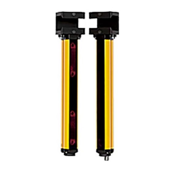
PSEN op2.1 L/ 2.2 TMuting Set INFORMATION This gives advice on applications and provides information on special fea tures. Overview The PSEN op2.1 LMuting Set consists of 1 x PSEN op2.3 LReflex 1 x PSEN op2.4 LReflector 2 x PSEN op muting bracket kit The PSEN op2.2 TMuting Set consists of 2 x PSEN op2.3 LReflex 2 x PSEN op2.4 LReflector 2 x PSEN op muting bracket kit The muting sets are suitable for expanding all safety light grids in the PSEN op4B/1 Series PSEN op2B/1 Series PSEN op4FA Series PSEN op4HA Series. Use the PSEN op2.1 LMuting Set To expand a linear model without integrated muting sensors into a linear module for muting in one direction or To expand a linear model for muting in one direction into a linear module for muting in two directions. Use the PSEN op2.2 TMuting Set To expand a linear model without integrated muting sensors into a linear module for muting in two directions. Operating Manual PSEN op2.1 L/ 2.2 TMuting Set 1003535EN01... -
Page 6: Safety
PSEN op2.1 L/ 2.2 TMuting Set Safety Intended use The muting set may only be used to expand a linear model without integrated muting sensors into a linear model for muting in one or two directions. The PSEN op2.1 LMuting Set may only be used in conjunction with the following light grids: To expand into a linear model for muting in one direction PSEN op2B/1 Ser PSEN op4B/1 Series PSEN op4FA Series PSEN op4HA Series PSEN op4B2050/1 PSEN op2B2050/1 PSEN op4FA14030/1 PSEN op4HA14030/1 PSEN op4B3080/1 PSEN op2B3080/1 PSEN op4FA14045/1 PSEN op4HA14045/1 PSEN op4B4090/1 PSEN op2B4090/1 PSEN op4FA14060/1 PSEN op4HA14060/1 PSEN op4B4120/1 PSEN op2B4120/1 PSEN op4FA14075/1 PSEN op4HA14075/1 PSEN op4FA14090/1 PSEN op4HA14090/1 PSEN op4FA14105/1 PSEN op4HA14105/1 PSEN op4FA14120/1 PSEN op4HA14120/1 PSEN op4FA14135/1 PSEN op4HA14135/1 PSEN op4FA14150/1 PSEN op4HA14150/1 PSEN op4FA14165/1 PSEN op4HA14165/1 PSEN op4FA14180/1 PSEN op4HA14180/1 To expand into a linear model for muting in two directions... - Page 7 PSEN op2.1 L/ 2.2 TMuting Set The PSEN op2.1 TMuting Set may only be used in conjunction with the following light grids: To expand into a linear model for muting in two directions PSEN op4B/1 Series PSEN op2B/1 Series PSEN op4FA Series PSEN op4HA Series PSEN op4B2050/1 PSEN op2B2050/1 PSEN op4FA14030/1 PSEN op4HA14030/1 PSEN op4B3080/1 PSEN op2B3080/1 PSEN op4FA14045/1 PSEN op4HA14045/1 PSEN op4B4090/1 PSEN op2B4090/1 PSEN op4FA14060/1 PSEN op4HA14060/1 PSEN op4B4120/1 PSEN op2B4120/1 PSEN op4FA14075/1 PSEN op4HA14075/1 PSEN op4FA14090/1 PSEN op4HA14090/1 PSEN op4FA14105/1 PSEN op4HA14105/1 PSEN op4FA14120/1 PSEN op4HA14120/1 PSEN op4FA14135/1 PSEN op4HA14135/1 PSEN op4FA14150/1 PSEN op4HA14150/1 PSEN op4FA14165/1 PSEN op4HA14165/1 PSEN op4FA14180/1 PSEN op4HA14180/1 The following is deemed improper use in particular: Any component, technical or electrical modification to the product Use of the product outside the areas described in this manual Use of the product outside the technical details (see chapter entitled "Technical De...
-
Page 8: Safety Regulations
PSEN op2.1 L/ 2.2 TMuting Set Safety regulations Use of qualified personnel The products may only be assembled, installed, programmed, commissioned, operated, maintained and decommissioned by competent persons. A competent person is someone who, because of their training, experience and current pro fessional activity, has the specialist knowledge required to test, assess and operate the work equipment, devices, systems, plant and machinery in accordance with the general standards and guidelines for safety technology. It is the company’s responsibility only to employ personnel who: Are familiar with the basic regulations concerning health and safety / accident preven tion Have read and understood the information provided in this description under "Safety" And have a good knowledge of the generic and specialist standards applicable to the specific application. Warranty and liability All claims to warranty and liability will be rendered invalid if The product was used contrary to the purpose for which it is intended Damage can be attributed to not having followed the guidelines in the manual Operating personnel are not suitably qualified Any type of modification has been made (e.g. exchanging components on the PCB boards, soldering work etc.). Disposal When decommissioning, please comply with local regulations regarding the disposal of electronic devices (e.g. Electrical and Electronic Equipment Act). Installation and wiring Installation Allocation of muting sensors to transmitter and receiver: – The passive muting sensor PSEN op Reflector must be installed on the transmitter – The active muting sensor PSEN op Reflex must be installed on the receiver Rx. Requirement for installing the muting sensors on the safety light grid: The PSEN op muting bracket kit (Order no. 630 824) must be attached to both units of the safety light grid. The safety light grid must already be attached to the mounting surface. Operating Manual PSEN op2.1 L/ 2.2 TMuting Set 1003535EN01... -
Page 9: Wiring
PSEN op2.1 L/ 2.2 TMuting Set Procedure Check the position of the mounting profile on the safety light grid and slide the mounting profile on both units of the safety light grid along to the correct position of the muting sensor. To do this, loosen the hexagonal screws. Then tighten up the hexagonal screws again. The mounting profiles should be at the same height. [1] Mounting profile for attaching the muting sensor [2] Safety light grid on mounting surface Fix the muting sensor with the small plates to the mounting profile. [1] Hexagonal screws for attaching the mounting pro file to the safety light grid [2] Allen screws for attaching the muting sensor to the mounting profile Wiring Use one of the supplied connection cables to wire the muting sensors: PSEN op cable M12 4p. 0.75m Lmuting for Lmuting PSEN op cableset for Tmuting a Wire the muting sensors as shown in the following diagrams. Operating Manual PSEN op2.1 L/ 2.2 TMuting Set 1003535EN01... - Page 10 PSEN op2.1 L/ 2.2 TMuting Set 24V DC Muting 1 Muting 2 Fig.: Wiring of 4 muting sensors on the receiver's 5pin connector 24V DC Muting 1 Muting 2 Fig.: Wiring of 2 muting sensors on the receiver's 5pin connector Legend [1] Wiring of muting sensor A1 on Pin 2 (Muting 1) of connector [2] Wiring of muting sensor A2 on Pin 2 (Muting 1) of connector [3] Wiring of muting sensor B1 on Pin 4 (Muting 2) of connector [4] Wiring of muting sensor B2 on Pin 4 (Muting 2) of connector Earthing of muting sensors Attach the earth connection in the drill hole provided on the side of the muting sensors us ing the screw provided. The drill holes for the earthing screw are on the right and left side of the muting sensors, at the same height. Identify the earthing contact using the adhesive label provided. Operating Manual PSEN op2.1 L/ 2.2 TMuting Set 1003535EN01...
-
Page 11: Commissioning
PSEN op2.1 L/ 2.2 TMuting Set Commissioning Orientation 1. Check that the safety light grid is aligned correctly and that the safety light grid is in nor mal operation. The green LED on the receiver, the yellow LED on the transmitter and both yellow LEDs on the receiver must be lit. 2. Make sure the DIP switches are set correctly for the choice of muting configuration. – If you are using the PSEN op2.1 LMuting Set, set DIP switches 2 and 6 to OFF. – If you are using the PSEN op2.1 TMuting Set, set DIP switches 2 and 6 to ON. 3. Use the LED to check the alignment of the muting sensors. 4. Modify the position of the muting sensors on the safety light grid until the red LEDs on the sensors go out (see diagram). – Vertical alignment of the muting sensors: Undo the hexagonal screws and move the mounting profile upwards. – Horizontal alignment of the muting sensors: Loosen the hexagonal screws and move the mounting profile within the slot hole for the hexagonal screws. Legend: [1]: Move the muting sensor upwards on the mounting profile for vertical alignment [2]: Move the muting sensor within the slot hole for horizontal alignment Operating Manual PSEN op2.1 L/ 2.2 TMuting Set 1003535EN01... -
Page 12: Led Support During Alignment
PSEN op2.1 L/ 2.2 TMuting Set LED support during alignment Display Meaning [1] Normal operation in Lights green Transmitter and receiver dicator are correctly aligned and the protected field is clear [2] High Align indicator Lights yellow Final upper transmitter lens is aligned with the receiver lens opposite [3] Safe condition indic Lights red Transmitter and receiver ator are not correctly aligned or protected field is inter rupted by an opaque ob ject [4] Low Align indicator Lights yellow Final lower transmitter lens is aligned with the receiver lens opposite LED indicators during alignment Receiver Prerequisites for muting To use muting, the following requirements apply: the muting lamp must not be defective, the muting inputs must be wired correctly (see Wiring [ 9]), the safety light grid must be in normal operation. If any of these requirements are not met, the safety light grid switches immediately to a safe condition when supply voltage is switched on. Checking the safety light grid Once the muting sensors have been installed and aligned, final inspections must be carried out before it can be put into service. INFORMATION This inspection may only be carried out by qualified personnel. -
Page 13: Set Muting Timeout
PSEN op2.1 L/ 2.2 TMuting Set Violate the protected field and check that – the OSSDs are switched off, – the red LED lights – the monitored machine is shut down. Check that the safety light grid's response time and the machine's stopping perform ance meet the specifications stated in the operating manual of the relevant safety light grid. Check that muting operates correctly. Access the protected field covered by the muting sensors. – The muting lamp on the safety light grid must light. – The red LEDs on the muting sensors must light. – The OSSDs must be switched off. – The monitored machine must be shut down. Set muting timeout Time monitoring for the muting function can be set to 10 minutes or to ∞ gestellt werden. When the unit is delivered, this is already preset to 10 minutes. CAUTION! If time monitoring for the muting function is set to ∞, the muting function is not cancelled until the muting sensors are no longer active. This setting does not comply with the specifications of EN ISO 614961. Avoid a situation in which permanent muting (on account of simultan eous errors or constantly interrupted muting sensors) will not be de tected. Procedure for setting to ∞ Set DIP switches 1 and 5 to OFF. Operating Manual PSEN op2.1 L/ 2.2 TMuting Set 1003535EN01... -
Page 14: Dimensions In Mm
PSEN op2.1 L/ 2.2 TMuting Set Dimensions in mm PSEN op2.1 L-Muting Set PSEN op2.1 T-Muting Set Legend: in mm Width of muting sensor Width of PSEN op muting bracket kit 55.5 Length of active muting arm PSEN op2.3 LReflex Width of the socket on the muting arms for attachment to the PSEN op muting bracket kit Length of the passive muting arm PSEN op2.4 LReflector Operating Manual PSEN op2.1 L/ 2.2 TMuting Set 1003535EN01... -
Page 15: Technical Details
PSEN op2.1 L/ 2.2 TMuting Set Dimensions PSEN muting Bracket Kit Technical details PSEN op LMuting Set and PSEN op TMuting Set General 630820 630821 Approvals Sensor's mode of operation optical optical Electrical data 630820 630821 Supply voltage Voltage 24,0 V 24,0 V Kind Voltage tolerance 20 %/+20 % 20 %/+20 % Protection class Optical data 630820 630821 Operating range 0,5 3,0 m 0,5 3,0 m Used wavelength range 650 nm 650 nm Environmental data 630820 630821 Ambient temperature Temperature range 10 55 °C 10 55 °C Storage temperature Temperature range 25 70 °C 25 70 °C... - Page 16 PSEN op2.1 L/ 2.2 TMuting Set Environmental data 630820 630821 Vibration In accordance with the standard EN 6006826 EN 6006826 Frequency 10,0 55,0 Hz 10,0 55,0 Hz Amplitude 0,35 mm 0,35 mm Shock stress In accordance with the standard EN 60068229 EN 60068229 Acceleration Duration 16 ms 16 ms Airgap creepage Pollution degree Protection type In accordance with the standard EN 60529 EN 60529 Housing IP65 IP65 Mechanical data 630820 630821 Material Aluminium Aluminium Dimensions Height 60,0 mm 60,0 mm Width 355,3 mm...
-
Page 17: Order Reference
PSEN op2.1 L/ 2.2 TMuting Set Environmental data 630822 630823 Vibration In accordance with the standard EN 6006826 EN 6006826 Frequency 10,0 55,0 Hz 10,0 55,0 Hz Amplitude 0,35 mm 0,35 mm Shock stress In accordance with the standard EN 60068229 EN 60068229 Acceleration Duration 16 ms 16 ms Airgap creepage Pollution degree Protection type In accordance with the standard EN 60529 EN 60529 Housing IP65 IP65 Mechanical data 630822 630823 Material Aluminium Aluminium Dimensions Height 60,0 mm 60,0 mm Width 299,8 mm... - Page 18 Back cover Support Technical support is available from Pilz round the clock. Americas Australia Scandinavia Brazil +61 3 95446300 +45 74436332 +55 11 97569-2804 Spain Canada Europe +34 938497433 Switzerland +1 888-315-PILZ (315-7459) Austria +43 1 7986263-0 +41 62 88979-30 Mexico...
Need help?
Do you have a question about the PSEN op2.1 L- and is the answer not in the manual?
Questions and answers