Sign In
Upload
Manuals
Brands
PerkinElmer Manuals
Laboratory Equipment
CLARUS 590 GC
PerkinElmer CLARUS 590 GC Manuals
Manuals and User Guides for PerkinElmer CLARUS 590 GC. We have
1
PerkinElmer CLARUS 590 GC manual available for free PDF download: User Manual
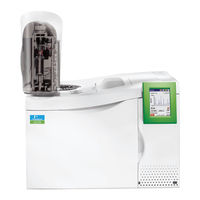
PerkinElmer CLARUS 590 GC User Manual (284 pages)
Brand:
PerkinElmer
| Category:
Laboratory Equipment
| Size: 6.65 MB
Table of Contents
Table of Contents
3
Introduction
11
About this Manual
13
Conventions Used in this Manual
13
About Notes, Cautions, and Warnings
13
Screen Abbreviations
16
Glossary of Clarus GC Terms
17
Autosampler Terms
17
Instrument-Specific Terms
17
Glossary of Chromatographic Terms
19
Touch Screen Navigation
21
Chapter Overview
23
Touch Screen
24
Tabs
25
Non-Configured Devices
25
Non-Installed Devices
26
Run Button
26
Manual Injection
27
Signal Button
28
Ignite Button
28
Autozero Button
28
Signal Plot
28
Signal Display and Scaling
29
Zero Display Button
29
Heated Zones
29
Injector and Detector Buttons
30
Oven Button
31
Aux Zone Buttons
31
Navigation Bar
32
Injectors
33
Program Buttons
33
Display Text
33
Pssi
34
Configuration Options
34
Temperature Program
34
Isothermal Program
36
Carrier Gas Program
36
Split Flow
38
Capillary Control off
38
Packed (Pkd)
39
Poc
42
Capillary (Cap)
42
Oven
43
Aux Zone
44
Detectors
45
Fi Dw
45
About Auto-Ignition
45
Auto-Ignite Process
46
Configuration Settings
47
Manual Pneumatics
47
Tcd
47
Ppc
48
Manual Pneumatics
48
Ecd
49
Ppc
50
Active Method
50
Configuration Screen
50
Manual Pneumatics
50
Pid
51
Ppc
51
Manual Pneumatics
51
Npd
52
Ppc
52
Manual Pneumatics
52
Fpd
53
Ppc
53
Manual Pneumatics
53
Timed Events
54
Events Tab
54
Timed Events Table
54
Add
55
Edit
55
Delete
55
Clear
56
Aux Zones
57
Heated Aux Zone
57
Pneumatic Auxiliary Zones
58
Using the Active Method
59
Overview
61
Editing the Active Method
62
Getting Ready to Edit the Active Method
63
Setting up Oven and Inlet Temperature Programs
64
Configuring the Equilibration Time (Init)
64
Setting a Coolant Timeout Value
65
Setting a Coolant Cut-In Temperature
65
Setting up an Isothermal Program
65
Setting up a One-Ramp Temperature Program
66
Holding an Oven Temperature
67
Setting Injector Temperatures
69
Displaying Injector Temperature Screens
69
Turning Injector Heaters on or off
70
Changing Injector Temperatures
70
Oven Temperature Programming Mode
71
Inlet Temperature Programming Mode
71
Setting up a One-Ramp Injector Program
72
Viewing/Setting Carrier Gas Pressure/Flow/Velocity
74
Carrier Gas Mass-Flow Controller Operation
74
Initial Carrier-Gas Setpoint
74
Carrier-Gas Program
74
Carrier-Gas Timed Events
75
Leak Checking
75
Setting PPC Carrier Gas Pressure in the PPC Version
75
Viewing or Adjusting Carrier Gas Pressure Using Manual Pneumatics
76
Setting PPC Carrier Gas Flow
77
Viewing/Adjusting Carrier Gas Flow Using Manual Pneumatics
78
Viewing/Setting Carrier Gas Velocity in the PPC Version
79
Setting the Septum Purge Mode and Offset
81
Setting up Valves
87
Setting the Split Mode Using PPC
87
Setting the Split Mode Using Manual Pneumatics
89
Set the Solenoid Valve for Split Operation
89
Measure and Adjust the Split Vent Flow
90
Set up the Splitless Mode for a CAP or PSS Injector
93
Setting the Splitless Mode Using PPC Modules
93
Splitless Injection with Pressure Pulse (Flow Pulse, Velocity Pulse) Technique
93
Creating a Pressure, Flow, or Velocity Pulse Method
93
Setting the Split Flow for Splitless Injection
96
Setting the Timed Events
97
Controlling the Autosampler
100
Autosampler Trays and Carousel
100
Autosampler Touch Screen
101
Start Button
102
Stop Button
102
Autosampler Buttons
104
Cleaning the 5-Μl and 50-Μl Syringe Plungers
106
Configuration Button
106
Auto Resume
106
Running Viscous Samples
106
Using Solvent Pre-Washes
107
Priority Button
107
About Waste and Wash Vials
107
Multi-Program Mode
107
Waste Vials
107
Wash Vials
108
About Sample Vials
108
Using a TCD with the Autosampler
108
Available Syringes
108
Setting up the Detectors
109
Overview
111
FI D Overview
113
Setting up a PPC FID
113
FID Setup Summary
113
Set the Air and Hydrogen Flows
114
Automatically Ignite the Flame
116
Manually Ignite the Flame
117
If the Flame Goes out During a Run
119
Setting up a Manual Pneumatics FID
120
FID Setup Summary
120
Connect a Flowmeter to the FID Collector
120
Adjust the Hydrogen Flow
121
Adjust the Air Flow
124
Ignite the Flame
124
If the Flame Goes out During a Run
125
Using the FID in Corrosive Environments
126
ECD Overview
127
Setting up an ECD
128
United States Government Regulations for Ecds
129
Special Instructions for ECD Cell Purchasers
129
Labels
129
Leak Testing
129
Cell Failure or Damage
129
Reporting Radiation Incidents, Theft or Loss
130
Other Requirements
130
United Kingdom Regulations
130
ECD Setup Summary
130
Vent the ECD Outlet
131
Adjust the Make-Up Gas Flow
132
Set the Make-Up Gas in the PPC Version
132
Adjust the Make-Up Gas in the Manual Pneumatics Version
133
TCD Overview
136
Setting up a TCD
136
TCD Setup Summary
136
Turn on the Oven and Detector Heaters
136
Equalize the Makeup and Reference Gas Flows
137
Set the Makeup and Reference Gas in the PPC Version
138
Adjust the Make-Up Gas in the Manual Pneumatics Version
139
Enter the TCD Bridge Current Range
140
Balance the Bridge
141
Using a TCD with the Autosampler or GSV
142
PID Overview
143
Setting up a PID
144
PID Setup Summary
144
Turn on the Oven and the Detector Heaters
144
Adjust the Make-Up Gas
145
Set the Make-Up Gas in the PPC Version
146
Turn on the UV Lamp
148
Optimize the Lamp Intensity
149
NPD Overview
150
Setting up a PPC NPD
151
Set the Hydrogen Flow and Air Flow for PPC
151
Setting up a Manual Pneumatics NPD
153
NPD Setup Summary
154
Disconnect the Hydrogen and Air Lines at the NPD Bulkhead
154
Adjust the Hydrogen Flow
155
Adjust the Air Flow
156
Reconnect the Air and Hydrogen Lines
156
NPD Bead Activation Procedure
157
Packed Column Setup
157
Capillary Column Setup
157
Preparing to Activate the NPD Bead
157
Activating the NPD Bead
159
Reactivate a Used NPD Bead
161
Operating Notes
161
FPD Overview
162
Setting up a PPC FPD
163
FPD Setup Summary
163
Configure the Linearizer and Signal Filter
163
Set the FPD Temperature
166
Set the Hydrogen Flow and Air Flow for PPC
167
Turn on the Photomultiplier Tube
169
Ignite the Flame
171
Setting up a Manual Pneumatics FPD
173
FPD Setup Summary
173
Configure the Linearizer and Signal Filter
173
Set the FPD Temperature
174
Attach a Flowmeter to the FPD
175
Adjust the Hydrogen Flow
175
Adjust the Air Flow
178
Turn on the Photomultiplier Tube
179
Ignite the Flame
180
Detector Temperatures
183
Range
184
Setting the PID or NPD Range
184
Changing the PID or NPD Range During a Run
184
Setting the TCD Current (Filament Current)
186
Changing TCD Polarity During a Run
188
Routing Detector Output
190
Rerouting Output
190
Attenuating Detector Signals Going to a Recorder
192
Optimizing a Detector Signal to an Integrator for Maximum Sample Dynamic Range
193
Matching Detector Signals with Your Integrator
194
Autozeroing a Detector
196
Using the Method Editor
197
Method Editor
199
Method Edit Mode
200
Oven Settings
201
Managing Methods
202
File Menu
202
New Method
202
Open Method
203
Save
203
Save as
204
Activate
206
Delete
206
Exit Editor
206
Using the Tools Menu
207
Using the Tools Menu . 209
209
Method Editor
209
Event Log
209
Maintenance
210
Configuration
212
Injectors (Deconfiguring and Configuring Injectors)
213
PSS - Programmed Split/Splitless Injector
214
Packed Injector
217
POC - Programmable on Column Injector
217
Capillary - Split/Splitless Injector
218
GSV - Gas Valve
218
Oven
219
Single Point Calibration
219
Detectors
220
Fid
222
Tcd
222
Ecd
224
Pid
224
Npd
224
Fpd
224
Output Configured
225
External Configuration
226
Run/Autosampler
226
Setup
227
Language Drop down Menu
228
Brightness Field
228
Date/Time Set
228
Startup
229
Sleep
229
Pneumatics
230
PPC Configure
230
Connecting the PPC Modules
231
PPC Connect
233
Define Detector Dialog
237
Define Aux
238
Reference Settings
239
Relays
239
Zeroing and Calibrating the PPC Modules
239
Zeroing the PPC Gas Modules
239
Setting the Reference Temperature and Pressure
242
Calibrating the Carrier Gas Modules
243
Calibrating the Detector Gas Modules
245
Calibrating the Flow Readout Using Manual Pneumatics
247
Calibrating the Oven Temperature
251
Calibrate the Reference Thermometer
251
Place the Thermometer Probe in the Oven
251
Equilibrate the Oven Temperature
252
Enter the Required Offset Value
254
Remove the Thermometer Probe
254
Utilities
255
Column Flow Calculator
256
Column Flow Calc Main Screen
257
Length
257
Diameter
257
Temp
257
Carrier Gas Name
257
Outlet Press
257
Suggested Velocity
257
Inlet Press
257
Flow Rate
258
Velocity
258
Split Flow Calculations Screen
258
Column Length Calculator
259
Stopwatch
259
Program (Max Oven Program Rates)
260
Release
260
Reset
261
Logout
261
About
261
Setting up a Typical Analysis
263
Overview
265
System Status Screen
266
Injectors . 267
267
Packed Column (PKD) Injector
267
Programmed Split/Splitless (PSS) Injector
268
Detector Settings
270
Flame Ionization Detector (FID)
270
Tcd
273
Autosampler
277
Index
279
Advertisement
Advertisement
Related Products
PerkinElmer clarus 500 gc
PerkinElmer CLARUS 600 GC
PerkinElmer CLARUS 680 GC
PerkinElmer Clarus SQ 8 MS Series
PerkinElmer Clarus SQ 8 T
PerkinElmer Clarus SQ 8 S
PerkinElmer Clarus 600/560 D MS
PerkinElmer 5184
PerkinElmer 5182
PerkinElmer 200A Series
PerkinElmer Categories
Laboratory Equipment
Measuring Instruments
Dispenser
Security Sensors
Amplifier
More PerkinElmer Manuals
Login
Sign In
OR
Sign in with Facebook
Sign in with Google
Upload manual
Upload from disk
Upload from URL