Advertisement
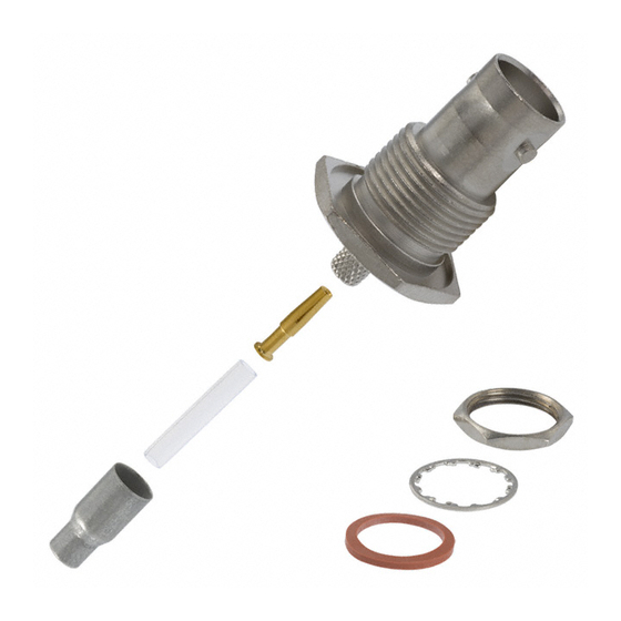
Pin Assembly (Size 5)
Pin Contact
Pin Ferrule
Pin Assembly (Size 12)
Pin Contact
Pin Ferrule
RG/U CABLE
CONTACT ASSEMBLY
STRIP
TYPE
SIZE
TYPE
DIM.
Pin
See
5
Fig. 2A
RD-316
Skt
(Double
Pin
Shielded)
See
12
Fig. 2B
Skt
▪TE Connectivity (TE) tool 601966-1 is equivalent for tool M22520/2-01 and positioners supplied by Daniels Mfg. Corp. See TE Instruction Sheet 408-7516.
1. INTRODUCTION
This instruction sheet covers the use of TE High Frequency Coaxial Contacts (Size 5 and Size 12) for Arinc
connectors. Read these instructions thoroughly to ensure the selected contacts are compatible with the cable
and with the center contact and ferrule tooling.
NOTE
Dimensions on this sheet are in metric units [with U.S. customary units in brackets]. Figures and illustrations are for reference
only and are not drawn to scale.
2. DESCRIPTION
(Figure 1)
The pin and socket connector assemblies shown in Figure 1 consist of a center contact and a pin or socket
body and a ferrule for shield braid is also included.
3. CONTACT SETUP PROCEDURE
Determine the cable size to be terminated and refer to the table in Figure 1 to select the pin and socket
connector assembly, center contact crimping tool, ferrule crimping tool, and stripping dimensions of the cable
(see Figure 2).
Arinc is a trademark.
© 2015 TE Connectivity family of companies
All Rights Reserved
*Trademark
TE Connectivity, TE connectivity (logo), and TE (logo) are trademarks. Other logos, product, and/or company names may be trademarks of their respective owners.
High Frequency Coaxial Contacts
(Size 5 and Size 12)
for Arinc Connectors
Pin Body
Pin Body
CENTER CONTACT TOOL
POSITIONER
PART NO.
TOOL NO.
2286269-1
2286268-1
M22520/2-01▪
2286271-1
2286270-1
Figure 1
TOOLING ASSISTANCE CENTER 1-800-722-1111
PRODUCT INFORMATION 1-800-522-6752
Socket Assembly (Size 5)
Socket Body
Socket Assembly (Size 12)
Socket Body
SELECTOR/
NO.
LOCATOR SETTING
7
K1933
5
3
K1934
3
This controlled document is subject to change.
For latest revision and Regional Customer Service,
visit our website at www.te.com.
Instruction Sheet
408-32166
Rev A
22 JAN 15
Socket Contact
Socket Ferrule
Socket Contact
Socket Ferrule
FERRULE TOOL
CRIMP
FERRULE
TOOL NO.
SECT
NO.
608650-1
w/Die Set
448642-3
Y141
B
354940-1
w/Die Set
1-1403102-4
58425-2
1 of 3
Advertisement
Table of Contents

Related Manuals for TE Connectivity RD-316


Summary of Contents for TE Connectivity RD-316
- Page 1 All Rights Reserved PRODUCT INFORMATION 1-800-522-6752 For latest revision and Regional Customer Service, *Trademark visit our website at www.te.com. TE Connectivity, TE connectivity (logo), and TE (logo) are trademarks. Other logos, product, and/or company names may be trademarks of their respective owners.
- Page 2 408-32166 7.87 ±0.25 [.310 ±.010] 5.84 ±0.25 [.230 ±.010] 5.97 ±0.25 [.235 ±.010] 4.57 ±0.25 [.180 ±.010] 3.55 ±0.25 3.30 ±0.25 Ferrule Ferrule [.140 ±.010] [.130 ±.010] Figure 2 NOTE The 8-indent (M22520/2-01) crimping tool is manufactured by Daniels Manufacturing Corporation. For information on tools and components for TE products, contact TE through the Tooling Assistance Center number listed at the bottom of page 1.
- Page 3 408-32166 3. Close handles on crimping tool until ratchet releases allowing handles to open. 4. Remove crimped contact. Ferrule (Figure 4) Refer to the table in Figure 1 and select the appropriate hand crimping tool for crimping the ferrule. The instruction sheet numbers are listed with the tools.
Need help?
Do you have a question about the RD-316 and is the answer not in the manual?
Questions and answers