Subscribe to Our Youtube Channel
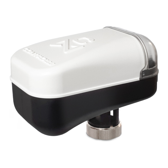
Summary of Contents for Controlli MVC503R-MB
- Page 1 Configuration Tool MVC503R-MB Release 1.0.0 Issue 10/20 DMP116e Controlli S.p.A. - 16010 Sant’Olcese (GE) Tel. 010 73 06 1 | Fax. 010 73 06 870/871 | www.controlli.eu...
-
Page 2: Table Of Contents
Summary INTRODUCTION ..............................3 INSTALLATION ..............................3 SETUP ................................. 4 MAIN WINDOW ..............................4 “MODBUS CONFIGURATION” BOX ........................5 “ACTUATOR CONFIGURATION” BOX ....................... 8 “VALVE CONFIGURATION” BOX ........................9 “ACTUATOR STATUS” BOX ..........................10 “ACTUATOR COMMAND ” BOX ........................11 SCAN MENU .............................. -
Page 3: Introduction
INTRODUCTION This configuration tool allows to configure and to monitor the MVC503R-MB actuator for correct commissioning of the system. The connection between the computer and the actuator is made via a USB / RS485 converter (LIBO-USB) with a serial communication bus and ModBus protocol (RTU). -
Page 4: Setup
SETUP The software can be started through the icon on the Desktop or through the Start → All path Programs → MVC503R- MB Configurator → Configurator menu. MAIN WINDOW When the software is executed, the following window will be displayed: From the “Language”... -
Page 5: Modbus Configuration" Box
To save a configuration file including all the values present into the software interface (values into the areas: Actuator Configuration, Valve Configuration and modbus parameters (baud rate, parity bit and stop bit)). To read from the configuration file the parameters and show them into the software interface. For the two last functions the Modbus connection with the actuator is not required. - Page 6 Select the field “Port (COM e LPT)” and note the serial port number related to the serial converter (in the example below: COM4). Modbus address of the device (Modbus Address). Modbus address is selectable via the first 8 dipswitches of the actuator following the encoding into the technical manual (example to select address 1, the dip switch issue 10/20...
- Page 7 The buttons “READ” and “WRITE” allow to set the Modbus communication parameters (baud-rate, parity and stop bit) on the actuator MVC503R-MB (slave), while the buttons “GET PARAM.” and “SET PARAM.” allow to set the communication parameters on the PC side (master).
-
Page 8: Actuator Configuration" Box
“ACTUATOR CONFIGURATION” BOX In this box it is possible to set the following configuration parameters of the actuator: Action: it allows to select direct or reverse action. Calibration: it allows to start the stroke calibration of the actuator; Press the “READ”... -
Page 9: Valve Configuration" Box
“VALVE CONFIGURATION” BOX In this box it is possible to set the following configuration parameters of the valve: PICV Valve Type: in case the actuator is installed on a LIBRA pressure independent control valve, it is possible to select the LIBRA range from the drop down menu in order to improve flow control. ... -
Page 10: Actuator Status" Box
“ACTUATOR STATUS” BOX In this box the actuator status and possible anomalies are shown: Status: it shows the current status of the actuator (initial positioning, calibrating, up end stroke, down end stroke, up positioning, down positioning) and the led status on the electronic board ... -
Page 11: Actuator Command " Box
Reset Actuator: SW reset of the actuator is executed by pressing the “RESET” button . Before to send others commands to the actuator it is necessary to wait the supercap recharge phase is completed. In case of changes in the actuator configuration parameters, press the “RESET” button to make the changes immediately effective. -
Page 12: Scan Menu
SCAN MENU This menu allows to perform a scan of the actuators inside the modbus network: The table in the left part of the windows can show the main actuator information of a subset of the actuators in the network. The scan can be executed by setting the start Modbus address and the end Modbus address of the actuator group and pressing the “READ”... -
Page 13: Configuration File Menu
CONFIGURATION FILE MENU This menu allows to save a .csv file containing all the configuration parameters of the connected actuator. In the drop-down menu are present the following items: Load configuration Write config. file Read config. file ... - Page 14 Read config. file: it allows to select a configuration file and to show all the parameters in the proper text boxes. Write config. file: it allows to save the configuration file (CSV) containing all the configuration parameters. Read and Write option can be done off-line (no Modbus connection is necessary). issue 10/20 DMP116e...


Need help?
Do you have a question about the MVC503R-MB and is the answer not in the manual?
Questions and answers