Advertisement
Quick Links
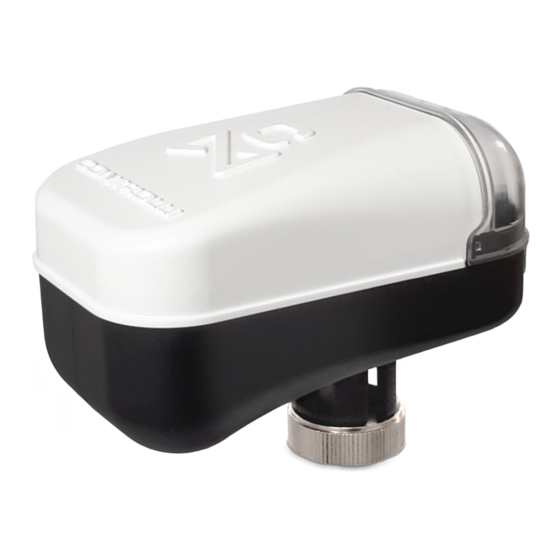
Servocomandi con funzione di ritorno in emergenza
Actuator with electronic emergency return
ISTRUZIONI DI MONTAGGIO / MOUNTING INSTRUCTIONS
INSTALLAZIONE / INSTALLATION
75°
1
Libra, V.XT, VSXT.PBP, VSBT.-VMBT.
Portare lo spintore del servocomando nella
posizione retratta
Set the actuator spindle in the retract position
75°
AVVERTENZE In caso di accoppiamento di MVC su una
valvola prodotta prima di Settembre 2019 in sostituzione
di un MVT occorre utilizzare il kit 55061.
VALVOLA (PRODUZIONE PRECEDENTE SETTEMBRE 2019) /
VALVE (PRODUCTION PREVIOUS SEPTEMBER 2019)
VSB.T-VMB.T
2-3TBB.T
2-3TGB.B
1
Emissione /1
Issue rev. a
a
st
1
2
2
75°
11/2020
Non utilizzare il servocomando se non accoppiato alla
valvola
Do not use the actuator if not coupled with the valve
1
1
3
2
VSB.T-VMB.T, 2-3TGB.B, 2-3TBB.T, 2TGA.BT
Allineare il foro dello spintore del servocomando con il foro
del dado (A), serrare la vite (B) attraverso il foro non filettato
del dato (A)
Align actuator spindle slot with the hole in locknut (A) , se-
NO
cure with bolt (B) through non threaded hole in locknut (A)
WARNING In case of MVC coupling on a valve produced
YES
before September 2019 to replace an MVT, must be used
the 55061 kit.
SERVOCOMANDO DA SOSTITUIRE /
ACTUATOR TO BE REPLACED
MVT203
MVT403
MVT503
1
CONTROLLI S.p.A. - 16010 Sant'Olcese (GE) - Italy
Tel. +39 010 73061 | Fax +39 010 7306870/871
info@controlli.eu | www.controlli.eu
MVC503R-MB
NO
SI
YES
3
2
B
A
NO
YES
KIT DI SOSTITUZIONE /
REPLACEMENT KIT
55061
B
A
DIM322
Advertisement

Subscribe to Our Youtube Channel
Related Manuals for Controlli MVC503R-MB


Summary of Contents for Controlli MVC503R-MB
- Page 1 ACTUATOR TO BE REPLACED REPLACEMENT KIT VSB.T-VMB.T MVT203 2-3TBB.T MVT403 55061 MVT503 2-3TGB.B Emissione /1 Issue rev. a 11/2020 DIM322 CONTROLLI S.p.A. - 16010 Sant’Olcese (GE) - Italy Tel. +39 010 73061 | Fax +39 010 7306870/871 info@controlli.eu | www.controlli.eu...
-
Page 2: Schemi Di Collegamento / Wiring Diagrams
VALVOLE SENZA MOLLA / VALVES WITHOUT SPRING VALVOLE CON MOLLA / VALVES WITH SPRING VALVOLE ALTRI 2-3TGB.B 2-3TBB.T 2TGA.BT VSXT-VMXT-VTXT VSXT.PBP VSBT.-VMBT. VSB.T-VMB.T VLX-VLX.P COSTRUTTORI / VALVES OF OTHER 1/2” 1/2” .. 2" 3/4” .. 2" 1/2” .. 3/4” 1 ½” 3/4”... - Page 3 AVVERTENZE DI COLLEGAMENTO CONNECTIONS WARNINGS R=100 - 120 Ohm cavo 3 fili / 3-wire cable Sistema di supervisione/ Supervisory system R=100 - 120 Ohm Device 1 Device 2 Device 3 Per un corretto cablaggio di rete si consiglia di prendere le seguen- For proper network cabling is recommended to take the following ti precauzioni: precautions:...
-
Page 4: Comando Manuale
PLUG & PLAY La calibrazione automatica viene eseguita al primo avvio. LINEAR/EQUIPERCENTAGE Actuator position characteristic is normally linear, but MVC503R-MB IMPOSTAZIONE VELOCITÀ SERVOCOMANDO allow to set an equipercentage behaviour allowing to make a linear La velocità del servocomando può essere regolata tramite Modbus tra 5 s/mm (impostazione di fabbrica) e 3 s/mm. - Page 5 MVC503R-MB consente di far funzionare una valvola lineare come una valvola equipercentrale. % Posizione Servocomando/Valvola % Actuator/Valve Position Lineare / Linear % Posizione regolazione Modbus / % Modbus Control Position valve working like an equipercentage valve. FUNZIONI DIAGNOSTICHE...
- Page 6 FUNZIONAMENTO LED Descrizione / Description DL1 (rosso/red) DL2 (verde/green) DL3 (giallo/yellow) Fase di apprendimento / Calibration Alternato 5 Hz / Alternate blinking 5 Hz Posizionamento iniziale / Initial posi- Alternato 1 Hz / Alternate blinking 1 Hz tioning Posizionamento UP / Running UP Lampeggiante 1 Hz / Blinking 1 Hz Fine corsa UP / End of stroke UP Posizionamento DOWN / Running...
- Page 7 PARAMETRI MODBUS Indi- Persis- Registro Modbus Descrizione Range Default RD/WR rizzo tenza "Versione firmware (è composto da 3 byte): 6678 1° byte: major version 6679 Versione firmware 0-FFFFFF 0xFFFFFF 2° byte: minor version 6680 3° byte: revision version" 6681 Primo avvio Rappresenta l'evento di prima accensione Valore 0xCF 0xFF...
-
Page 8: Modbus Parameters
MODBUS PARAMETERS Persis- Modbus Register Description Range Default RD/WR dress tence "Firmware version (composed of 3 bytes): 6678 byte: major version 6679 Firmware version 0-FFFFFF 0xFFFFFF byte: minor version 6680 byte: revision version" 6681 First power up Represents the first power up event 0xCF value 0xFF Represents the number of times a stroke error has... - Page 9 INDIRIZZO MODBUS INDIRIZZO MODBUS DIP8 DIP7 DIP6 DIP5 DIP4 DIP3 DIP2 DIP1 DIP8 DIP7 DIP6 DIP5 DIP4 DIP3 DIP2 DIP1 / MODBUS ADDRESS / MODBUS ADDRESS Impostazioni di fabbrica (default indirizzo 1) / Facto- ry setting (default address 1) Emissione /1 Issue rev.
- Page 10 INDIRIZZO MODBUS INDIRIZZO MODBUS DIP8 DIP7 DIP6 DIP5 DIP4 DIP3 DIP2 DIP1 DIP8 DIP7 DIP6 DIP5 DIP4 DIP3 DIP2 DIP1 / MODBUS ADDRESS / MODBUS ADDRESS Emissione /1 Issue rev. a 11/2020 DIM322...
- Page 11 INDIRIZZO MODBUS DIP8 DIP7 DIP6 DIP5 DIP4 DIP3 DIP2 DIP1 / MODBUS ADDRESS DIP9 FUNZIONE / FUNCTION Calibrazione automatica della corsa / Auto stroke calibration ATTENZIONE: quando inizia la calibrazione automatica della corsa, ATTENTION: When auto stroke calibration start move DIP9 to OFF. With spostare DIP9 su OFF.
Need help?
Do you have a question about the MVC503R-MB and is the answer not in the manual?
Questions and answers