
Related Manuals for Precor AMT12 Base


Summary of Contents for Precor AMT12 Base
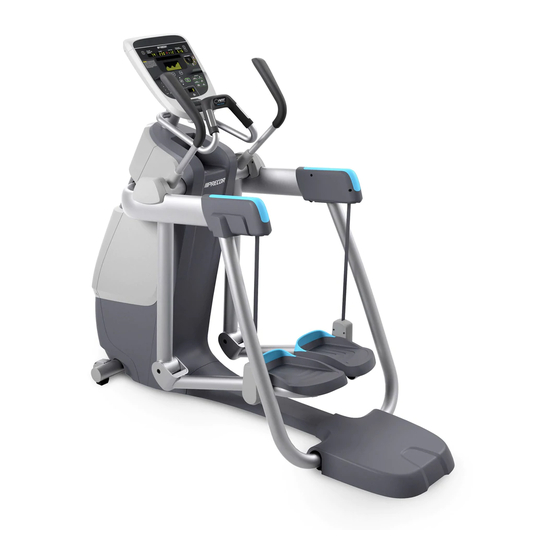
- Page 1 Service Manual AMT12 Base AMT800-16/18 Base AMT700-16/18 Base Open Stride and Fixed Stride Page 1 of 214 © 2012 Precor Incorporated, Unauthorized Reproduction and Distribution Prohibited by Law...
-
Page 2: Table Of Contents
Drive Input Belt Tension Adjustment ............................. 18 Procedure ................................... 18 Lift Motor Calibration Adjustment ............................21 Issues/symptoms ................................21 Tools required ................................... 21 Procedure ..................................21 Page 2 of 214 © 2012 Precor Incorporated, Unauthorized Reproduction and Distribution Prohibited by Law... - Page 3 Replacing the Lower PCA and Battery Bracket ........................128 Replacing the Battery ................................130 Replacing the Generator Belt ............................... 131 Replacing the Generator ..............................132 Replacing the Drive Input Pulley Belt ........................... 133 Page 3 of 214 © 2012 Precor Incorporated, Unauthorized Reproduction and Distribution Prohibited by Law...
- Page 4 Daily Maintenance ................................211 Weekly Maintenance ................................211 Quarterly Maintenance ............................... 211 On-Site Preventive Maintenance (Service Technician) ......................212 SYSTEM BLOCK DIAGRAM ..........................213 WIRING DIAGRAM ............................214 Page 4 of 214 © 2012 Precor Incorporated, Unauthorized Reproduction and Distribution Prohibited by Law...
- Page 5 AMT 12 Wiring Diagram ............................... 214 Page 5 of 214 © 2012 Precor Incorporated, Unauthorized Reproduction and Distribution Prohibited by Law...
-
Page 6: About This Document
About This Document Warning: This service manual is for use by Precor trained service providers only. If you are not a Precor Trained Servicer, you must not attempt to service any Precor Product; Call your dealer for service. This document contains information required to perform the majority of troubleshooting, and replacement procedures required to repair and maintain this product. -
Page 7: Things You Should Know
Anti-static kit Torque wrench, 200 in./lbs. Screwdriver set Torque wrench, 200 ft./lbs OTC 6673 Universal Belt Tension Gauge 4 - 6 gear puller Page 7 of 214 © 2012 Precor Incorporated, Unauthorized Reproduction and Distribution Prohibited by Law... -
Page 8: Parts And Exploded View Diagrams
Parts and Exploded View Diagrams For the latest exploded view, part number and part pricing information, visit the Precor Partner Website at http://www.precorconnect.com/ Page 8 of 214 © 2012 Precor Incorporated, Unauthorized Reproduction and Distribution Prohibited by Law... -
Page 9: Drive Belt Gauge Instructions
1-2 minutes and then re- check the tension. This will allow the belt to seat itself in the grooves of the pulley, and ensure tension is set correctly. Page 9 of 214 © 2012 Precor Incorporated, Unauthorized Reproduction and Distribution Prohibited by Law... - Page 10 If the tension is not set to the manufactures specifications, remove the tension gauge and adjust the belt tension. Repeat steps 1 through 4 until specifications are met. Page 10 of 214 © 2012 Precor Incorporated, Unauthorized Reproduction and Distribution Prohibited by Law...
-
Page 11: Warning And Caution Statements And General Safety Guidelines
Removing the tension from the flat belts will prevent accidental pinching. Safety Page 11 of 214 © 2012 Precor Incorporated, Unauthorized Reproduction and Distribution Prohibited by Law... - Page 12 AMT’s equipped with Cardio Theater PVS units will have external power supply and coaxial cable routed through the bottom of the unit to the top of the display console. Cord management must be maintained. Page 12 of 214 © 2012 Precor Incorporated, Unauthorized Reproduction and Distribution Prohibited by Law...
-
Page 13: Checking The Amt Operation
Accessing the P30 Diagnostic Software. (on page 58). System Settings 12 Check stride indicator for proper operation. 13 Check wireless and hand held heart rate functions. Page 13 of 214 © 2012 Precor Incorporated, Unauthorized Reproduction and Distribution Prohibited by Law... -
Page 14: Adjustment Procedures
3 The belt gauge should read approximately 130-140 lbs. If the belt tension is significantly high or low the belt tension may be adjusted by loosening or tightening the H-Brake adjustment bolt. Figure 51: H-Brake Belt and H-Brake Cam Page 14 of 214 © 2012 Precor Incorporated, Unauthorized Reproduction and Distribution Prohibited by Law... - Page 15 Page 15 of 214 © 2012 Precor Incorporated, Unauthorized Reproduction and Distribution Prohibited by Law...
-
Page 16: Generator Belt Tension Adjustment
Generator Belt Tension Specification Generat Tension or Belt 85 +/- 5 lbs (38.6 +/- 2.3 kgs) used* 60 - 75 lbs (27.2 - 34 kgs) Page 16 of 214 © 2012 Precor Incorporated, Unauthorized Reproduction and Distribution Prohibited by Law... - Page 17 9 Recheck the drive input belt and the generator belt tension, readjust if out-of-spec. See Drive Belt Gauge Instructions. 10 Replace the covers per procedure, Cover Replacement. Page 17 of 214 © 2012 Precor Incorporated, Unauthorized Reproduction and Distribution Prohibited by Law...
-
Page 18: Drive Input Belt Tension Adjustment
Drive Belt Gauge Instructions. Drive Belt Tension Specification Drive Tension Belt 135 +/- 5 lbs (61.2 +/- 2.3 kgs) used* 100 - 125 lbs (45.4 - 56.7 kgs) Page 18 of 214 © 2012 Precor Incorporated, Unauthorized Reproduction and Distribution Prohibited by Law... - Page 19 Pedal the AMT for approximately one minute. f Recheck the drive belt tension, readjust if needed. 4 Place the belt gauge on the generator belt. Page 19 of 214 © 2012 Precor Incorporated, Unauthorized Reproduction and Distribution Prohibited by Law...
- Page 20 Pedal the AMT for approximately one minute. f Recheck the generator belt tension, readjust if out-of-spec. 10 Replace the covers as per procedure, Cover Replacement. Page 20 of 214 © 2012 Precor Incorporated, Unauthorized Reproduction and Distribution Prohibited by Law...
-
Page 21: Lift Motor Calibration Adjustment
If the level 5 Clearance Gap is NOT within specification the lift motor needs to be calibrated, go to the Lift Motor Calibration procedure below. b. If the level 5 Clearance Gap is within specification, continue with the next step. Page 21 of 214 © 2012 Precor Incorporated, Unauthorized Reproduction and Distribution Prohibited by Law... - Page 22 Note: If the A/D values are slightly out-of-range but the gas spring level 5 Clearance Gap is within the specified limits ¼ to ¾ inch [6mm to 19mm]), there is no need to do a lift motor calibration. 10. Reinstall the LPCA cover. Page 22 of 214 © 2012 Precor Incorporated, Unauthorized Reproduction and Distribution Prohibited by Law...
- Page 23 11. Reinstall the front, left/right side, left/right bottom, center beam, and back covers, see Cover Replacement. 12. Verify operation and return to service. Page 23 of 214 © 2012 Precor Incorporated, Unauthorized Reproduction and Distribution Prohibited by Law...
- Page 24 18. Remove the lift motor extension tube from the lift arm assembly bracket. Remove the hitch pin and lift pivot pin, see the following figure Lift Motor Extension Tube Connection. Page 24 of 214 © 2012 Precor Incorporated, Unauthorized Reproduction and Distribution Prohibited by Law...
- Page 25 Lift Arm Extension Tube Connection below. Page 25 of 214 © 2012 Precor Incorporated, Unauthorized Reproduction and Distribution Prohibited by Law...
- Page 26 If greater than ¾ inch, remove the lift motor clevis pin, rotate the lift motor actuator tube ½ turn clockwise. Reinstall the motor clevis pin and verify the clearance is correct. Page 26 of 214 © 2012 Precor Incorporated, Unauthorized Reproduction and Distribution Prohibited by Law...
- Page 27 Reinstall the LPCA cover d. Reinstall the front, left/right side, left/right bottom, center beam, and back covers, see Cover Replacement. e. Verify operation and return to service. Page 27 of 214 © 2012 Precor Incorporated, Unauthorized Reproduction and Distribution Prohibited by Law...
-
Page 28: Replacement Procedures
1 Standing at the front of the AMT, push in and then downward on the cover gasket with your thumbs until the gasket locking tabs are free of the top cover, grasp the gasket and remove. The gasket is split Page 28 of 214 © 2012 Precor Incorporated, Unauthorized Reproduction and Distribution Prohibited by Law... - Page 29 With the heel of your hand, gently tap the back cover just below the top cover, see figure below. The top cover should release from the back cover, remove the top cover and set aside. Page 29 of 214 © 2012 Precor Incorporated, Unauthorized Reproduction and Distribution Prohibited by Law...
-
Page 30: Front Cover Removal
Place the heels of your hands just above the left and right side triangle markers. Gently tap the triangle markers with the palm of your hand, the locking tabs will release and the front can be removed. Page 30 of 214 © 2012 Precor Incorporated, Unauthorized Reproduction and Distribution Prohibited by Law... -
Page 31: Center Beam Cover Removal
Note: Do not lift the cover up right after the front cover tab releases, lifting up the cover too quickly may not allow the middle center beam tabs to clear the frame slots, damaging the tabs. Figure 70: Center Beam Cover Removal Page 31 of 214 © 2012 Precor Incorporated, Unauthorized Reproduction and Distribution Prohibited by Law... -
Page 32: Back Cover Removal
1 Grasp the top of the rear cover and pull back, the back cover will release from the locking tab and then the cover can be lifted out of the slots in the bottom covers. Page 32 of 214 © 2012 Precor Incorporated, Unauthorized Reproduction and Distribution Prohibited by Law... -
Page 33: Left And Right Side Cover Removal
1 Remove the eight #10 x ¾ inch screws that fasten the bottom covers to the frame. Figure 73: Left and Right Side Cover Screw Locations Page 33 of 214 © 2012 Precor Incorporated, Unauthorized Reproduction and Distribution Prohibited by Law... -
Page 34: Left And Right Bottom Cover Assembly
4 Push the bottom of the side cover in until the tabs of the side cover rest in the notches on the bottom cover. 5 Repeat the Side Cover Assembly procedure for the right side cover. Figure 75: Side Cover Assembly Page 34 of 214 © 2012 Precor Incorporated, Unauthorized Reproduction and Distribution Prohibited by Law... -
Page 35: Back Cover Assembly
Figure 77: Back Cover Locking Tab Page 35 of 214 © 2012 Precor Incorporated, Unauthorized Reproduction and Distribution Prohibited by Law... -
Page 36: Center Beam Cover Assembly
2 Fasten the two #10 x ¾ inch screws at the bottom corners of the front cover. Tighten the screws completely. Upper Arm Cover Replacement Figure 78: Upper Arm Covers Page 36 of 214 © 2012 Precor Incorporated, Unauthorized Reproduction and Distribution Prohibited by Law... - Page 37 4 Secure the replacement cover to the arm using the five screws removed in step 1. Finger Tighten screws in all locations before fully tightening screws. Figure 79: Upper Arm Cover Screw Locations Page 37 of 214 © 2012 Precor Incorporated, Unauthorized Reproduction and Distribution Prohibited by Law...
-
Page 38: Rear Flat Belt Terminal Cover Replacement
4 Fasten the outside and inside terminal cover to the flat belt terminal using the two #10-24 X 1.25 screws. Figure 80: Flat Belt Terminal Covers Page 38 of 214 © 2012 Precor Incorporated, Unauthorized Reproduction and Distribution Prohibited by Law... -
Page 39: Upper Arm Cam Cover Replacement
1 Position the rear edge of the top cover so that the clips on the top and back covers are engaged securely. 2 Gently snap the front edge of the top cover into place, using the heel of your hand if necessary. Page 39 of 214 © 2012 Precor Incorporated, Unauthorized Reproduction and Distribution Prohibited by Law... -
Page 40: Replacing The Belt Guard
3 Remove the inside and outside covers from the upper arm. 4 Repeat the process for the remaining upper arm covers. Figure 83: Upper Arm Cover Screw Locations Page 40 of 214 © 2012 Precor Incorporated, Unauthorized Reproduction and Distribution Prohibited by Law... - Page 41 5 Grasp the belt guard mounting ring's located on each side of the upper arm. Gently pull out and away from the grip connection ring's just enough to extend past the mounting bolt. Figure 84: Belt Guard and Upper Arm Page 41 of 214 © 2012 Precor Incorporated, Unauthorized Reproduction and Distribution Prohibited by Law...
- Page 42 Align the interlocking tabs of the front belt guard with the slots of the rear belt guard; rotate the halves together around the flat belt until the locking tabs are locked. Page 42 of 214 © 2012 Precor Incorporated, Unauthorized Reproduction and Distribution Prohibited by Law...
-
Page 43: Replacing The Upper Arm Grip
9 Replace the upper arm covers as per procedure, Upper Arm Cover Replacement. Replacing the Upper Arm Grip Upper Arm Grip Replacement Procedure Upper Arm Cover Removal Figure 88: Upper Arm Covers Page 43 of 214 © 2012 Precor Incorporated, Unauthorized Reproduction and Distribution Prohibited by Law... - Page 44 2 Remove the screw that fasten the outside upper arm covers to the upper arm. 3 Remove the inside and outside covers from the upper arm. 4 Repeat the process for the remaining upper arm covers. Page 44 of 214 © 2012 Precor Incorporated, Unauthorized Reproduction and Distribution Prohibited by Law...
- Page 45 5 Grasp the belt guard mounting ring's located on each side of the upper arm. Gently pull out and away from the grip connection ring's just enough to extend past the mounting bolt. Figure 90: Belt Guard and Upper Arm Page 45 of 214 © 2012 Precor Incorporated, Unauthorized Reproduction and Distribution Prohibited by Law...
- Page 46 8 Remove the two #10-24X.75 screws that secure the grip to the upper arm, there is one screws on each side of the upper arm. Page 46 of 214 © 2012 Precor Incorporated, Unauthorized Reproduction and Distribution Prohibited by Law...
- Page 47 9 Grasp the grip connecting ring located on each side of the upper arm, pull up and over the flat belt pulley mounting bolt to remove the grip. Page 47 of 214 © 2012 Precor Incorporated, Unauthorized Reproduction and Distribution Prohibited by Law...
- Page 48 Align the interlocking tabs of the smaller half with the slots of the larger half; rotate the halves together around the flat belt until the locking tabs are locked. Figure 94: Belt Guard Interlocking Tabs and Slots Page 48 of 214 © 2012 Precor Incorporated, Unauthorized Reproduction and Distribution Prohibited by Law...
-
Page 49: Replacing A Flat Belt Terminal
2 Rotate the top of the inside terminal cover down until it is below the stairarm pedal, pull to remove. 3 Repeat the process for the remaining rear flat belt terminal cover. Page 49 of 214 © 2012 Precor Incorporated, Unauthorized Reproduction and Distribution Prohibited by Law... - Page 50 7 Remove the mounting bolt and washer that secure the flat belt terminal to the stairarm, remove the flat belt terminal and anti-rotation disc. Figure 97: Flat Belt Terminal Removal Page 50 of 214 © 2012 Precor Incorporated, Unauthorized Reproduction and Distribution Prohibited by Law...
- Page 51 3 7/8 inches. Page 51 of 214 © 2012 Precor Incorporated, Unauthorized Reproduction and Distribution Prohibited by Law...
- Page 52 Rotate the top of the cover up and in to place. 2 Fasten the outside and inside terminal cover to the flat belt terminal using the two #10-24 X 1.25 screws. Page 52 of 214 © 2012 Precor Incorporated, Unauthorized Reproduction and Distribution Prohibited by Law...
-
Page 53: Replacing A Upper Arm Flat Belt Pulley
2 Remove the tension from the inner flat belt pulleys by lifting up on the stairarms, pulling the flat belts off the flat belt pulleys, and then gently setting the stairarm down. Upper Arm Cover Removal Page 53 of 214 © 2012 Precor Incorporated, Unauthorized Reproduction and Distribution Prohibited by Law... - Page 54 4 Remove the screw that fasten the outside upper arm covers to the upper arm. 5 Remove the inside and outside covers from the upper arm. 6 Repeat the process for the remaining upper arm covers. Page 54 of 214 © 2012 Precor Incorporated, Unauthorized Reproduction and Distribution Prohibited by Law...
- Page 55 7 Grasp the belt guard mounting ring's located on each side of the upper arm. Gently pull out and away from the grip connection ring's just enough to extend past the mounting bolt. Figure 103: Belt Guard and Upper Arm Page 55 of 214 © 2012 Precor Incorporated, Unauthorized Reproduction and Distribution Prohibited by Law...
- Page 56 10 Remove the 3/8-16 X 3 mounting bolt, the two washers and the 3/8-16 lock nut that secure the upper arm pulley to the upper arm. Figure 105: Upper Arm Flat Belt Pulley Mounting Page 56 of 214 © 2012 Precor Incorporated, Unauthorized Reproduction and Distribution Prohibited by Law...
- Page 57 14 Grasp the grip connecting ring located on each side of the upper arm grip, pull out and place the grip over the flat belt pulley mounting bolt. Page 57 of 214 © 2012 Precor Incorporated, Unauthorized Reproduction and Distribution Prohibited by Law...
- Page 58 Upper Arm Cover Installation 18 Secure the upper arm covers to the arm weldment using the five #10- 24X1.25 screws. Figure 108: Upper Arm Cover Screw Locations Page 58 of 214 © 2012 Precor Incorporated, Unauthorized Reproduction and Distribution Prohibited by Law...
- Page 59 19 Lift the stairarms and then thread the flat belts over the flat belt pulleys. 20 Replace the main body covers asp per procedure, Cover Replacement. Replacing a Stairarm Pedal Figure 109: Stairarm and Stairarm Pedal Page 59 of 214 © 2012 Precor Incorporated, Unauthorized Reproduction and Distribution Prohibited by Law...
-
Page 60: Replacing A Stairarm
Figure 110: Stairarm and Stairarm Pedal Screw Locations Replacing a Stairarm Figure 111: Stairarm and Front Arm Page 60 of 214 © 2012 Precor Incorporated, Unauthorized Reproduction and Distribution Prohibited by Law... -
Page 61: Stairarm Replacement Procedure
2 Rotate the top of the inside terminal cover down until it is below the stairarm pedal, pull to remove. 3 Repeat the process for the remaining rear flat belt terminal cover. Figure 112: Flat Belt Terminal Covers Page 61 of 214 © 2012 Precor Incorporated, Unauthorized Reproduction and Distribution Prohibited by Law... - Page 62 6 Once the screwdriver has locked the bearing preventing further rotation, fully remove the inside and outside mounting bolts. Remove the stairarm. Page 62 of 214 © 2012 Precor Incorporated, Unauthorized Reproduction and Distribution Prohibited by Law...
- Page 63 Stairarm Knuckle Cover Removal 9 Remove the two #10-24 X.75 screws that secure the stairarm knuckle cover to the stairarm and set aside the knuckle cover. Page 63 of 214 © 2012 Precor Incorporated, Unauthorized Reproduction and Distribution Prohibited by Law...
- Page 64 12 Torque the screws to 25 inch pounds, starting from the single screw at the end of the stairarm, then the two camp screws, finally the two rear pedal screws. Figure 117: Stairarm and Stairarm Pedal Screw Locations Page 64 of 214 © 2012 Precor Incorporated, Unauthorized Reproduction and Distribution Prohibited by Law...
- Page 65 300 inch pounds (25 ft-lbs) or 25 foot pounds. Figure 118: Flat Belt Terminal Removal Page 65 of 214 © 2012 Precor Incorporated, Unauthorized Reproduction and Distribution Prohibited by Law...
-
Page 66: Replacing The Flat Belts
100,000,000 and a stride count reset has not been issued through software diagnostics, the AMT will lock out the display with an out of service, replace flat belts message. Page 66 of 214 © 2012 Precor Incorporated, Unauthorized Reproduction and Distribution Prohibited by Law... - Page 67 Note: When the belts are replaced, it is required that all 4 flat belts be replaced at the same time. Figure 120: Flat Belts Precor recommends not swapping lower and upper PCA boards to troubleshoot, but if swapping is the only option to isolate a problem, swap only one PCA board at a time.
-
Page 68: Belt Replacement & Odometer Tracking Codes
Stride count greater than Display "Belts Change 100 million strides Required" Inside Flat Belt Replacement 1 Remove the main body covers as per procedure, Cover Replacement. Page 68 of 214 © 2012 Precor Incorporated, Unauthorized Reproduction and Distribution Prohibited by Law... - Page 69 6 Remove and discard the two 1/4-20X1 flat belt clamp screws and shims that secure the flat belt to the clamp. Figure 122: Front Belt Clamp Screw Removal Page 69 of 214 © 2012 Precor Incorporated, Unauthorized Reproduction and Distribution Prohibited by Law...
- Page 70 9 Remove and discard the two 1/4-20X1 flat belt cam clamp screws and shims that secure the flat belt to the clamp. Figure 124: Upper Inside Cam Screw Removal Page 70 of 214 © 2012 Precor Incorporated, Unauthorized Reproduction and Distribution Prohibited by Law...
- Page 71 12 Place the inside flat belt on the cam so the length of the flat belt is draped towards the back of the AMT. Make sure the smooth side of the flat belt contacts the cam and the segmented side is facing up. Page 71 of 214 © 2012 Precor Incorporated, Unauthorized Reproduction and Distribution Prohibited by Law...
- Page 72 15 Continue to work the flat belt loop and pin into the cam clamp until the side of the flat belt is resting next to the clamp screw. Ensure the pin is centered within the cam clamp. Page 72 of 214 © 2012 Precor Incorporated, Unauthorized Reproduction and Distribution Prohibited by Law...
- Page 73 If the flat belts are not long enough to route through the pulley's, skip the belt routing until the belt flat belt installation is completed Page 73 of 214 © 2012 Precor Incorporated, Unauthorized Reproduction and Distribution Prohibited by Law...
-
Page 74: Flat Belt Installation - Front Clamp
20 Continue to work the flat belt loop and pin into the terminal clamp until the side of the flat belt is resting next to the clamp screw. Ensure the pin is centered within the terminal clamp. Page 74 of 214 © 2012 Precor Incorporated, Unauthorized Reproduction and Distribution Prohibited by Law... - Page 75 24 Monitor the movement of the belt through the clamps until one or both ends of the flat belt has one belt segment extending beyond the flat belt clamp. Page 75 of 214 © 2012 Precor Incorporated, Unauthorized Reproduction and Distribution Prohibited by Law...
-
Page 76: Outside Flat Belt Replacement
28 If the flat belt was not re-routed through the pulley's in step 17, route them at this time. 29 Repeat the procedure for the remaining inside flat belt replacement. Outside Flat Belt Replacement Upper Arm Cover Removal Figure 132: Upper Arm Covers Page 76 of 214 © 2012 Precor Incorporated, Unauthorized Reproduction and Distribution Prohibited by Law... - Page 77 2 Remove the screw that fasten the outside upper arm covers to the upper arm. 3 Remove the inside and outside covers from the upper arm. 4 Repeat the process for the remaining upper arm covers. Page 77 of 214 © 2012 Precor Incorporated, Unauthorized Reproduction and Distribution Prohibited by Law...
- Page 78 1 Grasp the belt guard mounting ring's located on each side of the upper arm. Gently pull out and away from the grip connection ring's just enough to extend past the mounting bolt. Page 78 of 214 © 2012 Precor Incorporated, Unauthorized Reproduction and Distribution Prohibited by Law...
- Page 79 Upper Arm Grip Removal 4 Remove the two screws that secure the grip to the upper arm, there is one screw on each side of the upper arm. Page 79 of 214 © 2012 Precor Incorporated, Unauthorized Reproduction and Distribution Prohibited by Law...
- Page 80 Figure 137: Upper Arm Grip Removal 6 Repeat the process for the remaining upper arm grip. Rear Flat Belt Terminal Cover Page 80 of 214 © 2012 Precor Incorporated, Unauthorized Reproduction and Distribution Prohibited by Law...
- Page 81 Figure 139: Flat Belt Removal - Terminal 11 Using a screwdriver, push out the pin from the flat belt loop and clamp and then slide the flat belt Page 81 of 214 © 2012 Precor Incorporated, Unauthorized Reproduction and Distribution Prohibited by Law...
- Page 82 Flat Belt Removal - Upper Arm Cam procedure. 13 Remove the mounting bolt, the two washers and the nut that secure the upper arm pulley to the upper arm. Page 82 of 214 © 2012 Precor Incorporated, Unauthorized Reproduction and Distribution Prohibited by Law...
- Page 83 16 Remove and discard the two 1/4-20X1 screws and shims that secure the flat belt to the cam clamp. Figure 143: Upper Outside Cam Screw Removal Page 83 of 214 © 2012 Precor Incorporated, Unauthorized Reproduction and Distribution Prohibited by Law...
- Page 84 18 Grasp the loose end of the flat belt from the back end of the upper arm and then pull the belt Page 84 of 214 © 2012 Precor Incorporated, Unauthorized Reproduction and Distribution Prohibited by Law...
- Page 85 AMT. Make sure the smooth side of the flat belt contacts the cam and the segmented side is facing up. Figure 146: Outside Flat belt Routing - Cam Page 85 of 214 © 2012 Precor Incorporated, Unauthorized Reproduction and Distribution Prohibited by Law...
- Page 86 25 Slide the pulley shaft into the flat belt pulley and place one spacer on each side of the flat belt pulley. Ensure the belt goes over the top of the pulley. Insert the assembly into the upper arm. Page 86 of 214 © 2012 Precor Incorporated, Unauthorized Reproduction and Distribution Prohibited by Law...
- Page 87 Do not fully tighten at this time. Outside Flat Belt Alignment 32 The flat belts ends will now need to be adjusted to their final position before the flat belt clamp Page 87 of 214 © 2012 Precor Incorporated, Unauthorized Reproduction and Distribution Prohibited by Law...
- Page 88 38 Push one of the stairarm pedal's down to its lowest level. Measure the distance from the bottom of the stairarm tube to the top of the center beam frame, the distance between the stairarm tube and the Page 88 of 214 © 2012 Precor Incorporated, Unauthorized Reproduction and Distribution Prohibited by Law...
- Page 89 43 Secure the upper arm grip to the upper arm using the two #10-24X.75 screws. 44 Repeat the process for the remaining upper arm grip. Page 89 of 214 © 2012 Precor Incorporated, Unauthorized Reproduction and Distribution Prohibited by Law...
- Page 90 Upper Arm Cover Installation 46 Secure the upper arm covers to the arm weldment using the five #10- 24X1.25 screws. Figure 153: Upper Arm Cover Screw Locations Page 90 of 214 © 2012 Precor Incorporated, Unauthorized Reproduction and Distribution Prohibited by Law...
-
Page 91: Replacing The Front Arm Assemblies - With Flat Belts And Press Fit Cams (After 4/3/2013)
The gasket is split At the back to facilitate removal. Page 91 of 214 © 2012 Precor Incorporated, Unauthorized Reproduction and Distribution Prohibited by Law... - Page 92 The top cover should release from the back cover, remove the top cover and set aside. Figure 156: Top Cover 1 Remove the two #10 x ¾ inch screws located at the bottom corners of front cover. Page 92 of 214 © 2012 Precor Incorporated, Unauthorized Reproduction and Distribution Prohibited by Law...
- Page 93 5 Pull the center beam cover back toward you until the cover is free from the frame. Note: Do not lift the cover up right after the front cover tab releases, lifting up the cover too quickly Page 93 of 214 © 2012 Precor Incorporated, Unauthorized Reproduction and Distribution Prohibited by Law...
- Page 94 8 Rotate the bottom of the side cover towards the back of the AMT to remove. 9 Repeat steps 1 and 2 to remove the right side cover. Page 94 of 214 © 2012 Precor Incorporated, Unauthorized Reproduction and Distribution Prohibited by Law...
- Page 95 It may be necessary to adjust the position of the vertical handlebar to gain access to the upper arm cam cover screws. Page 95 of 214 © 2012 Precor Incorporated, Unauthorized Reproduction and Distribution Prohibited by Law...
- Page 96 18 Repeat the steps for the remaining rear flat belt terminal covers. Figure 161: Flat Belt Terminal Covers 1 Remove the two bolts that adjust and secure the flat belt clamps to the flat belt terminals. Page 96 of 214 © 2012 Precor Incorporated, Unauthorized Reproduction and Distribution Prohibited by Law...
- Page 97 3 Remove the screw that fasten the outside upper arm covers to the upper arm. 4 Remove the inside and outside covers from the upper arm. Figure 163: Upper Arm Cover Screw Locations Page 97 of 214 © 2012 Precor Incorporated, Unauthorized Reproduction and Distribution Prohibited by Law...
- Page 98 2 Remove the two screws that secure the grip to the upper arm, there is one screw on each side of the upper arm. Figure 164: Upper Arm Grip Screw Locations Page 98 of 214 © 2012 Precor Incorporated, Unauthorized Reproduction and Distribution Prohibited by Law...
- Page 99 3 Grasp the grip connecting ring located on each side of the upper arm, pull up and over the flat belt pulley mounting bolt to remove the grip. Page 99 of 214 © 2012 Precor Incorporated, Unauthorized Reproduction and Distribution Prohibited by Law...
- Page 100 6 The belt guard assembly is two interlocking halves and needs to be separated before it can be removed from flat belt: a) Lower the belt guard down just below the upper arm. Page 100 of 214 © 2012 Precor Incorporated, Unauthorized Reproduction and Distribution Prohibited by Law...
- Page 101 8 Slide out the upper arm pulleys, the two spacers, and the pulley shaft from the upper arms. Figure 169: Upper Arm Flat Belt Pulley Removed Page 101 of 214 © 2012 Precor Incorporated, Unauthorized Reproduction and Distribution Prohibited by Law...
- Page 102 11 Once the screwdriver has locked the bearing preventing further rotation, fully remove the inside and outside mounting bolts. Remove the stairarm. Page 102 of 214 © 2012 Precor Incorporated, Unauthorized Reproduction and Distribution Prohibited by Law...
- Page 103 14 Remove the tie rod mounting bolts and washers that secure each upper tie rod end to the front arm assemblies. Figure 172: Tie Rods Page 103 of 214 © 2012 Precor Incorporated, Unauthorized Reproduction and Distribution Prohibited by Law...
- Page 104 16 Remove the six bolts that secure the upper main shaft clamp to the lower main shaft clamp. Remove the top main shaft clamp. Figure 174: Main Shaft Clamp Bolts Page 104 of 214 © 2012 Precor Incorporated, Unauthorized Reproduction and Distribution Prohibited by Law...
- Page 105 17 With assistance, lift the front arm and flat belts out of the lower main shaft clamp and upper arm. 18 Remove the other front arm and flat belts. Page 105 of 214 © 2012 Precor Incorporated, Unauthorized Reproduction and Distribution Prohibited by Law...
- Page 106 Note: the flat belt must be routed over the strut in the front arm assembly. Failure to route the flat belt over the strut will cause severe damage to the flat belt. The Figure below illustrates the correct flat belt routing. Page 106 of 214 © 2012 Precor Incorporated, Unauthorized Reproduction and Distribution Prohibited by Law...
- Page 107 Figure 177: Front Arm Shaft and Main Clamp 21 Insert and finger tighten the shoulder bolts that secure the outside cam tubes to the upper arms. Figure 178: Front Arm Mounting Bolt Page 107 of 214 © 2012 Precor Incorporated, Unauthorized Reproduction and Distribution Prohibited by Law...
- Page 108 Flat Belt Pulley Installation 25 Slide the pulley shaft into the flat belt pulley and place one spacer on each side of the flat belt Page 108 of 214 © 2012 Precor Incorporated, Unauthorized Reproduction and Distribution Prohibited by Law...
- Page 109 Align the interlocking tabs of the smaller half with the slots of the larger half; rotate the halves together around the flat belt until the locking tabs are locked. Page 109 of 214 © 2012 Precor Incorporated, Unauthorized Reproduction and Distribution Prohibited by Law...
- Page 110 83 foot pounds or 1000 inch pounds. 38 Remove the screwdriver from the drain hole. 39 Repeat the steps for the remaining stairarm. Figure 181: Stairarm and Front Arm Screw Locations Page 110 of 214 © 2012 Precor Incorporated, Unauthorized Reproduction and Distribution Prohibited by Law...
- Page 111 40 Ensue the flat belts are routed correctly through the pulleys. See illustration below for proper flat belt routing. Figure 182: Flat Belts 41 Secure the front flat belts terminals to platform. Figure 183: Front Belt Clamps Page 111 of 214 © 2012 Precor Incorporated, Unauthorized Reproduction and Distribution Prohibited by Law...
- Page 112 Adjusting the Stairarm Pedal Height 43 Hand tighten the two bolts and washers that adjust and secure the flat belt clamp to the flat belt terminal. Page 112 of 214 © 2012 Precor Incorporated, Unauthorized Reproduction and Distribution Prohibited by Law...
- Page 113 46 Fully tighten the stop bolt, torque to 300 inch pounds (25 ft-lbs) or 25 foot pounds. 47 Replace the flat belt guard. 48 Replace the cam covers. 49 Replace the body covers. Page 113 of 214 © 2012 Precor Incorporated, Unauthorized Reproduction and Distribution Prohibited by Law...
-
Page 114: Replacing A Front Arm Assembly - Without Flat Belts And Non-Press Fit Cams (Prior To 4/3/2013)
3 Remove the two #10-24X1.25 screws that secure the upper arm cam covers to the upper arm, then remove the covers. It may be necessary to adjust the position of the vertical handlebar to gain access to Page 114 of 214 © 2012 Precor Incorporated, Unauthorized Reproduction and Distribution Prohibited by Law... - Page 115 7 Remove and discard the two 1/4-20X1 flat belt cam clamp screws and shims that secure the flat belt Page 115 of 214 © 2012 Precor Incorporated, Unauthorized Reproduction and Distribution Prohibited by Law...
- Page 116 10 Remove the tie rod mounting bolt and washer that secures the upper tie rod end to the upper arm axle. Figure 190: Tie Rods Page 116 of 214 © 2012 Precor Incorporated, Unauthorized Reproduction and Distribution Prohibited by Law...
- Page 117 12 Remove the six bolts that secure the upper main shaft clamp to the lower main shaft clamp. Remove the top main shaft clamp. Figure 192: Main Shaft Clamp Bolts Page 117 of 214 © 2012 Precor Incorporated, Unauthorized Reproduction and Distribution Prohibited by Law...
- Page 118 For example, mark the outside cam with a "O" and the inside with a "I". Figure 193: Front Arm Cam Orientation Page 118 of 214 © 2012 Precor Incorporated, Unauthorized Reproduction and Distribution Prohibited by Law...
- Page 119 2 Fasten the flat belt cam to the front arm tube using the two replacement screws and shims, torque to 120 in pounds or 10 foot pounds. Figure 194: Flat Belt Cam Screws & Cam Screws Page 119 of 214 © 2012 Precor Incorporated, Unauthorized Reproduction and Distribution Prohibited by Law...
- Page 120 Figure 196: Front Arm Shaft and Main Clamp Page 120 of 214 © 2012 Precor Incorporated, Unauthorized Reproduction and Distribution Prohibited by Law...
- Page 121 7 Secure the front arm shaft to the upper arm using the shoulder bolt, torque to 300 inch pounds (25 ft-lbs) or 25 foot pounds. Figure 198: Front Arm Mounting Bolt Page 121 of 214 © 2012 Precor Incorporated, Unauthorized Reproduction and Distribution Prohibited by Law...
- Page 122 4 1/2 inches. Using a straight edge and permanent marker draw a line across the flat belt at 4 1/2 inches. Repeat this process for the other end of the flat belt. Page 122 of 214 © 2012 Precor Incorporated, Unauthorized Reproduction and Distribution Prohibited by Law...
- Page 123 6 Continue to work the flat belt loop and pin into the cam clamp until the side of the flat belt is resting next to the clamp screw. Ensure the pin is centered within the cam clamp. Figure 202: Upper Inside Cam Pin Install Page 123 of 214 © 2012 Precor Incorporated, Unauthorized Reproduction and Distribution Prohibited by Law...
- Page 124 10 Slide the flat belt loop into the cam clamp until the side of the flat belt is resting next to the clamp screw. Push the pin into the flat belt loop; ensure the pin is centered within the cam clamp. Page 124 of 214 © 2012 Precor Incorporated, Unauthorized Reproduction and Distribution Prohibited by Law...
- Page 125 15 Continue to work the flat belt loop and pin into the cam clamp until the side of the flat belt is resting next to the clamp screw. Figure 205: Upper Outside Cam Pin Page 125 of 214 © 2012 Precor Incorporated, Unauthorized Reproduction and Distribution Prohibited by Law...
- Page 126 20 Remove the screwdriver from the drain hole. Figure 206: Stairarm and Front Arm Screw Locations 21 Lift the stairarm and then thread the flat belts over the flat belt pulleys. Page 126 of 214 © 2012 Precor Incorporated, Unauthorized Reproduction and Distribution Prohibited by Law...
-
Page 127: Replacing The Lower Board
Removing the Lower PCA 1 Attach the wrist ESD strap to your arm, and then connect the ground wire of the wrist strap to a Page 127 of 214 © 2012 Precor Incorporated, Unauthorized Reproduction and Distribution Prohibited by Law... -
Page 128: Replacing The Lower Pca And Battery Bracket
Figure 208: Lower PCA Replacing the Lower PCA and Battery Bracket Procedure 1 Remove the main body covers as per procedure, Cover Replacement. Page 128 of 214 © 2012 Precor Incorporated, Unauthorized Reproduction and Distribution Prohibited by Law... - Page 129 Note: Ensure that the wires are not pinched between the generator bracket and the lower PCA battery bracket. Figure 210: Lower PCA & Battery Bracket Mounting Page 129 of 214 © 2012 Precor Incorporated, Unauthorized Reproduction and Distribution Prohibited by Law...
-
Page 130: Replacing The Battery
5 Connect the red wire battery cable to the terminal on the battery marked with a (+) or red square. 6 Connect the black wire battery cable to the terminal on the battery marked with a (-) or black square. Page 130 of 214 © 2012 Precor Incorporated, Unauthorized Reproduction and Distribution Prohibited by Law... -
Page 131: Replacing The Generator Belt
6 Loosen the Step-Up pulley adjustment bolt until tension has been removed from the input pulley belt and has sufficient slack so that the belt may be removed from the Step-Up pulley. Figure 212: Generator Page 131 of 214 © 2012 Precor Incorporated, Unauthorized Reproduction and Distribution Prohibited by Law... -
Page 132: Replacing The Generator
3 Disconnect the cables from the lower PCA and then remove the lower PCA and battery bracket as per procedure, Replacing the Lower PCA and Battery Bracket. 4 Remove the generator tension adjustment bolt, washer, lock nut and tension plate. Page 132 of 214 © 2012 Precor Incorporated, Unauthorized Reproduction and Distribution Prohibited by Law... -
Page 133: Replacing The Drive Input Pulley Belt
4 Loosen the generator adjustment bolt until the top of the bracket slots are resting on the generator mounting bolts. 5 Loosen the Step-Up pulley mounting bolt. Page 133 of 214 © 2012 Precor Incorporated, Unauthorized Reproduction and Distribution Prohibited by Law... - Page 134 4 Lift the stairarms and then thread the flat belts over the flat belt 5 Replace the covers as per procedure, Cover Replacement Page 134 of 214 © 2012 Precor Incorporated, Unauthorized Reproduction and Distribution Prohibited by Law...
-
Page 135: Replacing The Step-Up Pulley
8 Remove the snap ring that secures the Step-Up pulley to the axle, remove the Step-Up pulley and wave washer. 9 Place the wave washer on the axle and then the replacement Step-Up pulley, secure the Step-Up Page 135 of 214 © 2012 Precor Incorporated, Unauthorized Reproduction and Distribution Prohibited by Law... -
Page 136: Replacing The Crank Arm
Remove the crank arm bolt, washer and crank arm. Torque the mounting bolt to 300 inch pounds (25 ft-lbs) or 25 foot pounds. Page 136 of 214 © 2012 Precor Incorporated, Unauthorized Reproduction and Distribution Prohibited by Law... - Page 137 4 Install the crank arm pinch bolt, washer and lock nut. Torque the pinch bolt and lock nut to 300 inch pounds (25 ft-lbs) or 25 foot pounds. Page 137 of 214 © 2012 Precor Incorporated, Unauthorized Reproduction and Distribution Prohibited by Law...
- Page 138 Remove the crank arm bolt, washer and crank arm. Torque the mounting bolt to 300 inch pounds (25 ft-lbs) or 25 foot pounds. Page 138 of 214 © 2012 Precor Incorporated, Unauthorized Reproduction and Distribution Prohibited by Law...
- Page 139 7 Install the crank arm pinch bolt, washer and lock nut. Torque the pinch bolt and lock nut to 300 inch pounds (25 ft-lbs) or 25 foot pounds. Page 139 of 214 © 2012 Precor Incorporated, Unauthorized Reproduction and Distribution Prohibited by Law...
- Page 140 Figure 235: Crank Arm Flat Belt Pulley 9 Lift the stairarms and thread the flat belts through the pulleys. 10 Replace the covers as per procedure, Cover Replacement. Page 140 of 214 © 2012 Precor Incorporated, Unauthorized Reproduction and Distribution Prohibited by Law...
-
Page 141: Replacing The Drive Input Pulley
6 Loosen the adjustment bolt for the Step-Up pulley until tension has been removed from the input pulley belt and it can be removed from the pulleys. Figure 237: Step-Up pulley Page 141 of 214 © 2012 Precor Incorporated, Unauthorized Reproduction and Distribution Prohibited by Law... - Page 142 8 On the crank arm side of the drive input, remove the snap ring from the flat pulley shaft located on to the drive input pulley, remove the pulley and wave washer. Page 142 of 214 © 2012 Precor Incorporated, Unauthorized Reproduction and Distribution Prohibited by Law...
- Page 143 11 Remove the screw and square washer that secures the drive input pulley assembly to the drive input housing. Pull the drive input pulley out of the housing. Page 143 of 214 © 2012 Precor Incorporated, Unauthorized Reproduction and Distribution Prohibited by Law...
- Page 144 Remove the crank arm Page 144 of 214 © 2012 Precor Incorporated, Unauthorized Reproduction and Distribution Prohibited by Law...
- Page 145 16 Install the crank arm pinch bolt, washer and lock nut. Torque the pinch bolt and lock nut to 300 inch pounds (25 ft-lbs) or 25 foot pounds. Page 145 of 214 © 2012 Precor Incorporated, Unauthorized Reproduction and Distribution Prohibited by Law...
- Page 146 19 Lift the stairarms and then thread the flat belts over the flat belt pulleys. 20 Go to "Inspecting and Adjusting the Drive Input Belt Tension" procedure and tension the Page 146 of 214 © 2012 Precor Incorporated, Unauthorized Reproduction and Distribution Prohibited by Law...
-
Page 147: Replacing The Lift Arm Housing
6 Loosen the adjustment bolt for the Step-Up pulley until tension has been removed from the input pulley belt and it can be removed from the pulleys. Figure 250: Step-Up pulley Page 147 of 214 © 2012 Precor Incorporated, Unauthorized Reproduction and Distribution Prohibited by Law... - Page 148 9 Rotate the gas spring down and out of the way of the lift motor. Page 148 of 214 © 2012 Precor Incorporated, Unauthorized Reproduction and Distribution Prohibited by Law...
- Page 149 Figure 252: lift motor Hitch Pin and Mounting Pin Page 149 of 214 © 2012 Precor Incorporated, Unauthorized Reproduction and Distribution Prohibited by Law...
- Page 150 Removing the flat belt pulley will allow access to the lift motor mounting bolt. 14 Remove the lift motor mounting bolt and remove the lift motor. Figure 253: lift motor Mounting Page 150 of 214 © 2012 Precor Incorporated, Unauthorized Reproduction and Distribution Prohibited by Law...
- Page 151 Do not use a hammer or mallet to remove the crank arm. Figure 255: Crank Arm Bolt Removal/ Installation Page 151 of 214 © 2012 Precor Incorporated, Unauthorized Reproduction and Distribution Prohibited by Law...
- Page 152 Note: If necessary a rubber mallet can be used to dislodge the input pulley assembly from the housing by tapping on the input shaft. Figure 257: Drive Input Assembly Page 152 of 214 © 2012 Precor Incorporated, Unauthorized Reproduction and Distribution Prohibited by Law...
- Page 153 Figure 258: Drive Input Assembly Alignment 20 Remove the four mounting bolts and washers that secure the flat belt clamps to the Lift Arm. Page 153 of 214 © 2012 Precor Incorporated, Unauthorized Reproduction and Distribution Prohibited by Law...
- Page 154 21 Remove the five mounting bolts that secure the left and right side arm housings to the input housing. Figure 260: Lift Arm Mounting Bolts 22 Separate the left and right side arm housings from the input housing. Page 154 of 214 © 2012 Precor Incorporated, Unauthorized Reproduction and Distribution Prohibited by Law...
- Page 155 Figure 262: Drive Input Assembly Alignment 26 Replace the drive input belt over the drive input pulley and the Step-Up pulley. Page 155 of 214 © 2012 Precor Incorporated, Unauthorized Reproduction and Distribution Prohibited by Law...
- Page 156 28 Install the crank arm pinch bolt, washer and lock nut. Torque the pinch bolt and lock nut to 300 inch pounds (25 ft-lbs) or 25 foot pounds. Page 156 of 214 © 2012 Precor Incorporated, Unauthorized Reproduction and Distribution Prohibited by Law...
- Page 157 36 Lift the stairarms and then thread the flat belts over the flat belt pulleys. 37 Go to "Inspecting and Adjusting the Drive Input Belt Tension" procedure and tension the drive and generator belts to the specified tension. Page 157 of 214 © 2012 Precor Incorporated, Unauthorized Reproduction and Distribution Prohibited by Law...
- Page 158 39 Replace the covers as per procedure, Cover Replacement. lift motor Installation 42 Attach the replacement lift motor to the frame using the 3/8-16 mounting bolt. Page 158 of 214 © 2012 Precor Incorporated, Unauthorized Reproduction and Distribution Prohibited by Law...
- Page 159 The lift level number must be 2 and the physical measurement must be 1-1/4 inches for the calibration to be correct. Page 159 of 214 © 2012 Precor Incorporated, Unauthorized Reproduction and Distribution Prohibited by Law...
- Page 160 49 Press the gas spring onto the mounting stud and secure the gas spring to the upper mounting stud by pushing in on the tension clip. Page 160 of 214 © 2012 Precor Incorporated, Unauthorized Reproduction and Distribution Prohibited by Law...
-
Page 161: Replacing The Drive Input Housing
2 Remove the tension from the inner flat belt pulleys by lifting up on the stairarms, pulling the flat belts off the flat belt pulleys, and then gently setting the stairarm down. 3 Loosen the two generator mounting bolts. Page 161 of 214 © 2012 Precor Incorporated, Unauthorized Reproduction and Distribution Prohibited by Law... - Page 162 6 Loosen the adjustment bolt for the Step-Up pulley until tension has been removed from the input pulley belt and it can be removed from the pulleys. Page 162 of 214 © 2012 Precor Incorporated, Unauthorized Reproduction and Distribution Prohibited by Law...
- Page 163 9 Rotate the gas spring down and out of the way of the lift motor. Page 163 of 214 © 2012 Precor Incorporated, Unauthorized Reproduction and Distribution Prohibited by Law...
- Page 164 12 Remove the lift motor mounting pin. If the Incline is jammed or has excessive pressure on the pin, it may be necessary to drive the pin out of the lift motor tube and lift arm assembly using a punch and rubber mallet. Page 164 of 214 © 2012 Precor Incorporated, Unauthorized Reproduction and Distribution Prohibited by Law...
- Page 165 Removing the flat belt pulley will allow access to the lift motor mounting bolt. 14 Remove the lift motor mounting bolt and remove the lift motor. Figure 277: lift motor Mounting Page 165 of 214 © 2012 Precor Incorporated, Unauthorized Reproduction and Distribution Prohibited by Law...
- Page 166 Do not use a hammer or mallet to remove the crank arm. Figure 279: Crank Arm Bolt Removal/ Installation Page 166 of 214 © 2012 Precor Incorporated, Unauthorized Reproduction and Distribution Prohibited by Law...
- Page 167 Note: If necessary a rubber mallet can be used to dislodge the input pulley assembly from the housing by tapping on the input shaft. Figure 281: Drive Input Assembly Page 167 of 214 © 2012 Precor Incorporated, Unauthorized Reproduction and Distribution Prohibited by Law...
- Page 168 21 Remove the four 3/8-16 X 3 mounting bolts and washers that secure the flat belt clamps to the Lift Arm. Figure 283: Lift Arm and Belt Clamps Page 168 of 214 © 2012 Precor Incorporated, Unauthorized Reproduction and Distribution Prohibited by Law...
- Page 169 22 Remove the five 5/16-18X1 mounting bolts that secure the left and right side arm housings to the input housing. Figure 284: Lift Arm Mounting Bolts 23 Separate the left and right side arm housings from the input housing. Page 169 of 214 © 2012 Precor Incorporated, Unauthorized Reproduction and Distribution Prohibited by Law...
- Page 170 25 Fasten the replacement drive input housing to the frame using the four mounting bolts removed in step 9, torque to 160 inch pounds. Note: Ensure the drive input alignment tab is position to the left side. Page 170 of 214 © 2012 Precor Incorporated, Unauthorized Reproduction and Distribution Prohibited by Law...
- Page 171 Make sure that the square washer does not contact the drive input pulley after installation, test by spinning the drive input pulley through its full range. Page 171 of 214 © 2012 Precor Incorporated, Unauthorized Reproduction and Distribution Prohibited by Law...
- Page 172 31 Install the crank arm pinch bolt, washer and lock nut. Torque the pinch bolt and lock nut to 300 inch pounds (25 ft-lbs) or 25 foot pounds. Page 172 of 214 © 2012 Precor Incorporated, Unauthorized Reproduction and Distribution Prohibited by Law...
- Page 173 Make sure the snap ring is fully seated into the shaft groove. Figure 292: Crank Arm Flat Belt Pulley 36 Lift the stairarms and then thread the flat belts over the flat belt pulleys. Page 173 of 214 © 2012 Precor Incorporated, Unauthorized Reproduction and Distribution Prohibited by Law...
- Page 174 The lift level number must be 2 and the physical measurement must be 1-1/4 inches for the calibration to be correct. Page 174 of 214 © 2012 Precor Incorporated, Unauthorized Reproduction and Distribution Prohibited by Law...
- Page 175 44 Press the gas spring onto the mounting stud and secure the gas spring to the upper mounting stud by pushing in on the tension clip. Figure 299: Gas Spring Page 175 of 214 © 2012 Precor Incorporated, Unauthorized Reproduction and Distribution Prohibited by Law...
-
Page 176: Replacing A Tie Rod
2 Remove the tie rod mounting bolt and washer that secures the lower tie rod end to the cam assembly. 3 Remove the tie rod mounting bolt and washer that secures the upper tie rod end to the upper arm axle. Page 176 of 214 © 2012 Precor Incorporated, Unauthorized Reproduction and Distribution Prohibited by Law... -
Page 177: Replacing The Stride Dial Sensor
3 Remove the two screws that secure the stride bracket to the frame and then remove the stride dial assembly. Figure 301: Stride Dial Assembly Page 177 of 214 © 2012 Precor Incorporated, Unauthorized Reproduction and Distribution Prohibited by Law... - Page 178 7 Reconnect the stride dial cable connector to the stride dial sensor, ensure the cable is routed and secured away from the H-Brake cam stops. Page 178 of 214 © 2012 Precor Incorporated, Unauthorized Reproduction and Distribution Prohibited by Law...
-
Page 179: Replacing The H-Brake Belt
Figure 303: H-Brake Belt and H-Brake Cam Procedure 1 Remove the covers per procedure, Cover Replacement. 2 Remove the Brake tension bolt, the two washers and nut. Page 179 of 214 © 2012 Precor Incorporated, Unauthorized Reproduction and Distribution Prohibited by Law... - Page 180 8 Slide the clamp onto the cam and fasten the clamps together using the H-Brake tension bolt, washers and nut. H-Brake Belt Tensioning 9 Place a belt gauge on the H-brake belt. Figure 305: H-Brake Belt Tension Gauge Page 180 of 214 © 2012 Precor Incorporated, Unauthorized Reproduction and Distribution Prohibited by Law...
- Page 181 10 The belt gauge should read approximately 130-140 lbs. If the belt tension is significantly high or low the belt tension may be adjusted by loosening or tightening the H-Brake adjustment bolt. 11 Replace the covers per procedure, Cover Replacement. Page 181 of 214 © 2012 Precor Incorporated, Unauthorized Reproduction and Distribution Prohibited by Law...
-
Page 182: Replacing The H-Brake Cam Assembly
4 Slide the left side belt clamp off the cam towards the right and remove. Stride Dial Removal 5 Disconnect the stride dial cable connector from the stride dial PCA. Page 182 of 214 © 2012 Precor Incorporated, Unauthorized Reproduction and Distribution Prohibited by Law... - Page 183 7 Remove the tie rod mounting bolts and washers that secure each lower tie rod end to the cam assembly. Figure 309: Tie Rods H-Brake Cam Removal and Installation Page 183 of 214 © 2012 Precor Incorporated, Unauthorized Reproduction and Distribution Prohibited by Law...
- Page 184 Figure 311: Tie Rods Stride Dial Assembly Installation 11 Secure the stride dial assembly to the frame with the two screws, do not fully tighten the screws. Page 184 of 214 © 2012 Precor Incorporated, Unauthorized Reproduction and Distribution Prohibited by Law...
- Page 185 14 Reconnect the stride dial cable connector to the stride dial sensor, ensure the cable is routed and secured away from the H-Brake cam stops. Page 185 of 214 © 2012 Precor Incorporated, Unauthorized Reproduction and Distribution Prohibited by Law...
- Page 186 18 Slide the clamp onto the cam and fasten the clamps together using the H-Brake tension bolt, washers and nut. H-Brake Belt Tensioning 19 Place a belt gauge on the H-brake belt. Page 186 of 214 © 2012 Precor Incorporated, Unauthorized Reproduction and Distribution Prohibited by Law...
-
Page 187: Replacing The H-Brake Drum Assembly
1 Remove the covers as described per procedure, Cover Replacement. H-Brake Belt Removal 2 Remove the H-Brake tension bolt, the two washers and nut. Figure 314: H-Brake Belt Assembly Page 187 of 214 © 2012 Precor Incorporated, Unauthorized Reproduction and Distribution Prohibited by Law... - Page 188 7 Rotate the gas spring down and out of the way of the lift motor. Page 188 of 214 © 2012 Precor Incorporated, Unauthorized Reproduction and Distribution Prohibited by Law...
- Page 189 Figure 316: lift motor Hitch Pin and Pivot Pin Page 189 of 214 © 2012 Precor Incorporated, Unauthorized Reproduction and Distribution Prohibited by Law...
- Page 190 H-Brake into the frame. The following steps will describe the removal and installation of the H-Brake Drum for both configuration. Page 190 of 214 © 2012 Precor Incorporated, Unauthorized Reproduction and Distribution Prohibited by Law...
- Page 191 21 Hand tighten the replacement H-Brake assembly to the frame using the 5/16-18 X 4 bolt and washer removed in the previous step. 22 Fasten the screw that secures the H-Brake drum assembly to the frame. Page 191 of 214 © 2012 Precor Incorporated, Unauthorized Reproduction and Distribution Prohibited by Law...
- Page 192 23 Torque the H-Brake mounting bolt to 600 inch pounds (50 ft-lbs). Page 192 of 214 © 2012 Precor Incorporated, Unauthorized Reproduction and Distribution Prohibited by Law...
- Page 193 Replacing the Lower PCA and Battery Bracket. 3 Access the incline Lift Test portion of the Diagnostic Program, see Accessing the P30 Diagnostic Software., P80 Settings. Page 193 of 214 © 2012 Precor Incorporated, Unauthorized Reproduction and Distribution Prohibited by Law...
- Page 194 8 Press the gas spring onto the mounting stud and secure the gas spring to the upper mounting stud by pushing in on the tension clip. Figure 322: Gas Spring Page 194 of 214 © 2012 Precor Incorporated, Unauthorized Reproduction and Distribution Prohibited by Law...
- Page 195 15 Slide the clamp onto the cam and fasten the clamps together using the H-Brake tension bolt, washers and nut. H-Brake Belt Tensioning 16 Place a belt gauge on the H-brake belt. Figure 323: H-Brake Belt Tension Gauge Page 195 of 214 © 2012 Precor Incorporated, Unauthorized Reproduction and Distribution Prohibited by Law...
-
Page 196: Replacing The Gas Spring
CROSSRAMP (or stride height) to level 1. 3. Remove the LPCA cover. 4. Disconnect the lift motor power cable from the LPCA board. Page 196 of 214 © 2012 Precor Incorporated, Unauthorized Reproduction and Distribution Prohibited by Law... - Page 197 It may help to wiggle and rotate the gas shock while removing. Gas Spring Installation Page 197 of 214 © 2012 Precor Incorporated, Unauthorized Reproduction and Distribution Prohibited by Law...
- Page 198 Adjustment procedure. 7. Reinstall the LPCA cover. 8. If the covers were removed, reinstall all removed covers. 9. Verify machine operation and return to service. Page 198 of 214 © 2012 Precor Incorporated, Unauthorized Reproduction and Distribution Prohibited by Law...
-
Page 199: Replacing The Lift Motor
If the pin is jammed or has excessive pressure on the pivot pin, it may be necessary to use a rubber mallet and pin punch to drive the pin out of the lift arm assembly bracket. Page 199 of 214 © 2012 Precor Incorporated, Unauthorized Reproduction and Distribution Prohibited by Law... - Page 200 Figure: Lift Motor Flat Belt Pulley 8. Remove the lift motor 1/2” hex head mounting bolt and remove the lift motor, see Lift Motor Mounting Bolt below. Page 200 of 214 © 2012 Precor Incorporated, Unauthorized Reproduction and Distribution Prohibited by Law...
- Page 201 3. Reinstall the lift motor extension tube into the lift arm assembly bracket and secure using the lift motor pivot pin and hitch pin, See figure: lift Motor Extension Tube Removal below. Page 201 of 214 © 2012 Precor Incorporated, Unauthorized Reproduction and Distribution Prohibited by Law...
- Page 202 6. Access the Hardware Validation diagnostics menu (51765761), select CROSSRAMP TEST, and set the CROSSRAMP (or stride height) to level 2. This positions the jack screw to the correct level 2 calibration length. Page 202 of 214 © 2012 Precor Incorporated, Unauthorized Reproduction and Distribution Prohibited by Law...
- Page 203 Choose the adjustment rotation direction (CW or CCW) that results in the final installation closest to the extension tube calibration gap 1 1/4” specification. c. Remove the ratchet strap. Page 203 of 214 © 2012 Precor Incorporated, Unauthorized Reproduction and Distribution Prohibited by Law...
- Page 204 11. Reinstall the LPCA cover, see Replacing the Lower PCA and Battery. 12. Reinstall the front, left/right side, eft/right bottom, Center beam, and back covers, see Cover Replacement. 13. Verify operation and return to service. Page 204 of 214 © 2012 Precor Incorporated, Unauthorized Reproduction and Distribution Prohibited by Law...
-
Page 205: Troubleshooting
50 strides per minute, all three voltage readings will be approximately 40 VAC - 45 VAC. 3 If any of the readings in step 2 are significantly low, replace the generator. If you have performed all of the above tests and are unable to resolve the problem, contact Precor customer support. Generator Operation Verification Test Use this procedure to verify the generator operating condition. - Page 206 8 If the readings are still incorrect, replace the three phase generator. 9 Reconnect the red battery wire removed in step 3. 10 Replace the right side cover as per, Cover Replacement Page 206 of 214 © 2012 Precor Incorporated, Unauthorized Reproduction and Distribution Prohibited by Law...
-
Page 207: Troubleshooting The Incline System
If the fuse is good or replacing the fuse does not correct the problem, continue with step 5. Figure 63: Lower PCA Fuse Locations Page 207 of 214 © 2012 Precor Incorporated, Unauthorized Reproduction and Distribution Prohibited by Law... - Page 208 9 If the voltage measurements in step 5 are correct and the motor does not move replace the lift motor. If the either voltage measurement in step 5 is significantly low, replace the motor. 10 If you have performed all of the above tests and are unable to resolve the problem, contact Precor customer support 11 Enter the diagnostic program per P80 System Tests.
- Page 209 16 If the readings in steps 14 and 15 are significantly high or low, replace the lift motor. Calibrate the lift motor per, Calibrating the lift motor. Page 209 of 214 © 2012 Precor Incorporated, Unauthorized Reproduction and Distribution Prohibited by Law...
-
Page 210: Troubleshooting The Comm Data Cable
If the unit works properly, replace the interconnect cable. 6 If you have performed all of the procedures above and have been unable to correct the problem, call Precor customer support. Page 210 of 214 © 2012 Precor Incorporated, Unauthorized Reproduction and Distribution Prohibited by Law... -
Page 211: Preventive Maintenance
Regular Preventive Maintenance (Owner) Cleanliness of the AMT and its operating environment will keep maintenance problems and service calls to a minimum. Precor recommends that you perform the following preventive maintenance schedule. After Each Use ♦ Wipe down the covers, handlebars and stairarms with a damp cloth. -
Page 212: On-Site Preventive Maintenance (Service Technician)
♦ Visually examine all wires and check connectors and wire connections. Secure connections and replace wiring as necessary. ♦ Cardio Theater cord management must be observed. Page 212 of 214 © 2012 Precor Incorporated, Unauthorized Reproduction and Distribution Prohibited by Law... -
Page 213: System Block Diagram
System Block Diagram Page 213 of 214 © 2012 Precor Incorporated, Unauthorized Reproduction and Distribution Prohibited by Law... -
Page 214: Wiring Diagram
Wiring Diagram AMT 12 Wiring Diagram Page 214 of 214 © 2012 Precor Incorporated, Unauthorized Reproduction and Distribution Prohibited by Law...
Need help?
Do you have a question about the AMT12 Base and is the answer not in the manual?
Questions and answers