Table of Contents
Advertisement
Advertisement
Table of Contents

Related Manuals for Precor AMT 800-Series


Summary of Contents for Precor AMT 800-Series
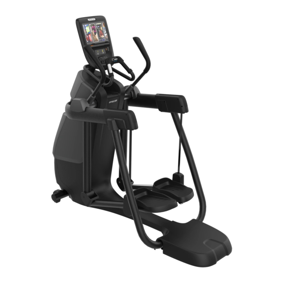
- Page 1 Assembling and Maintaining 800-Series ® Adaptive Motion Trainers ®...
- Page 4 Preva Business Suite, the accompanying printed materials, any copies of such software, and all data collected via the Preva Business Suite, are exclusively owned by Precor or its suppliers, as the case may be. Precor is widely recognized for its innovative, award-winning designs of exercise equipment.
-
Page 5: Important Safety Instructions
Note: This product is intended for commercial use. The display apparatus (hereinafter referred to as the console) is intended to be shipped with new Precor exercise equipment (hereinafter referred to as the base unit). It is not packaged for individual sale. -
Page 6: Safety Precautions
Assembling and Maintaining AMT 800-Series Adaptive Motion Trainers Safety Precautions Always follow basic safety precautions when using this equipment to reduce the chance of injury, fire, or damage. Other sections in this manual provide more details of safety features. Be sure to read these sections and observe all safety notices. - Page 7 Important Safety Instructions Care should be taken when mounting or dismounting the equipment. For Treadmills: Do not use typing or web surfing features while walking at speeds that exceed a slow and relaxed leisurely pace. Always stabilize yourself by holding a stationary handle bar while using typing or web surfing features.
- Page 8 Assembling and Maintaining AMT 800-Series Adaptive Motion Trainers SPACING—The below minimum spacing recommendations are based on a combination of the ASTM (U.S.) voluntary standards and EN (European) regulations as of October 1, 2012, for access, passage around, and emergency dismount: –...
- Page 9 350 pounds (160 kg). Use the equipment only for its intended purpose as described in this manual. Do not use accessory attachments that are not recommended by Precor. Such attachments may cause injuries. Do not operate the equipment where aerosol (spray) ...
-
Page 10: Educating Users
The batteries within self-powered equipment contain materials that are considered hazardous to the environment. Federal law requires proper disposal of these batteries. If you plan to dispose of your equipment, contact Precor Commercial Products Customer Support for information regarding battery removal. Refer to Obtaining Service. -
Page 11: Regulatory Notices For The Rfid Module
Important Safety Instructions Regulatory Notices for the RFID Module When equipped with a control console as described in this document, this equipment may include a radio-frequency identification (RFID) module. The RFID module has been certified to operate at temperatures between -20°C and 85°C (-4°F and 185°F). -
Page 12: European Applications
Assembling and Maintaining AMT 800-Series Adaptive Motion Trainers Industry Canada This device complies with RSS-210:2007 of the Spectrum Management & Telecommunications Radio Standards Specification. Operation is subject to the following two conditions: (1) this device may not cause harmful interference, and (2) this device must accept any interference received, including interference that may cause undesired operation. -
Page 13: Regulatory Notices For Cardiovascular Exercise Equipment
The regulatory information in this section applies to the exercise equipment and its control console. Safety Approvals for Cardiovascular Equipment Precor equipment has been tested and found to comply with the following applicable safety standards. Cardiovascular Type Equipment: CAN/CSA, IEC, EN 60335-1 (Household and similar ... - Page 14 Assembling and Maintaining AMT 800-Series Adaptive Motion Trainers Industry Canada This Class A digital apparatus complies with Canadian ICES-003. Cet appareil numérique de la classe A est conforme à la norme NMB-003 du Canada. ATTENTION: Haute Tension Débranchez avant de réparer...
-
Page 15: Electrical Recommendations: All Equipment Excluding Treadmills
Important Safety Instructions Electrical Recommendations: All Equipment Excluding Treadmills Note: This is a recommendation only. NEC (National Electric Code) guidelines or local region electric codes must be followed. For equipment fitted with a P80 console or Personal Viewing System (PVS) screen a separate power connection is required. -
Page 16: Obtaining Service
Do not attempt to service the equipment except for maintenance tasks. If any items are missing, contact your dealer. For more information regarding customer support numbers or a list of Precor authorized service centers, visit the Precor web site at http://www.precor.com. Obtaining Updated Documentation Current Precor product documentation is available at http://www.precor.com/productmanuals. -
Page 17: Table Of Contents
Table of Contents Important Safety Instructions ........... 3 Safety Precautions ................4 Educating Users ..................8 Hazardous Materials and Proper Disposal ........8 Product Recycling and Disposal ............8 Regulatory Notices for the RFID Module ........9 Regulatory Notices for Cardiovascular Exercise Equipment ..11 Electrical Recommendations: All Equipment Excluding Treadmills .............. - Page 18 Assembling and Maintaining AMT 800-Series Adaptive Motion Trainers Maintenance ................59 Daily Cleaning ..................59 Daily Inspection .................. 60 Cleaning the P80 Console and Display ......... 61 Weekly Maintenance ................ 62 Monthly Maintenance ..............62 Changing the Belt (AMT Only) ............63 Storing the Chest Strap ..............
-
Page 19: Assembling The Amt
Provide ample space around the unit. Assemble the equipment according to the guidelines in this manual to ensure you do not void the Precor Limited Warranty. Important: Any damage caused during installation is not covered by the Precor Limited Warranty. -
Page 20: Hardware Kit (Not To Scale)
The hardware kit shipped with this equipment contains the fasteners and other hardware components shown in the following table. Before you begin assembly, make sure that your hardware kit is complete. If not, please contact Precor Customer Support. Fasteners Quantity Nylon lock nuts (⁵... -
Page 21: Required Tools
Assembling the AMT Required Tools #2 Phillips screwdriver Rubber mallet SAE standard socket set Wire cutter Two #1 Phillips screwdrivers Torque wrench (calibrated in inch-pounds, and including ³ ₁₆-inch hex wrench bit) Unpacking the AMT DANGER Do not attempt to connect electrical power until all assembly procedures are complete and the... -
Page 22: Adding The Side Arm Supports
Assembling and Maintaining AMT 800-Series Adaptive Motion Trainers Adding the Side Arm Supports In the next procedure you will need the following pieces of hardware: Two side arm supports Two inner side arm covers Two outer side arm covers ... - Page 23 Assembling the AMT 3. Slide one ⁵ ₁₆-inch flat washer and one ⁵ ₁₆-inch sleeve over one of the ⁵ ₁₆-inch x 3¹ ₂-inch hex head bolts. Figure 3: Adding the sleeve and washer 4. Insert the ⁵ ₁₆-inch x 3¹ ₂-inch hex head bolt, with the washer and sleeve, into the screw hole on the inside of the right-hand side arm.
- Page 24 Assembling and Maintaining AMT 800-Series Adaptive Motion Trainers 6. Place the flanges of the two side arm supports against the sets of screw holes on the center support. Insert a screwdriver through the middle holes in both flanges and the center support to keep the screw holes aligned.
- Page 25 Assembling the AMT 8. On the opposite side of the center support from the handles of the screwdrivers, insert the four ⁵ ₁₆-inch x 3¹ ₂-inch hex head bolts. Attach a ⁵ ₁₆-inch nylon lock nut to each bolt. Partially tighten the fasteners, then remove the screwdrivers.
- Page 26 Assembling and Maintaining AMT 800-Series Adaptive Motion Trainers 11. Remove the two #10 x ³⁄₄-inch Phillips-head screws securing the upper back corner of the inner plastic molding to the end of the right side arm. Figure 7: Removal of screws from inner plastic molding 12.
- Page 27 Assembling the AMT 13. Repeat the previous two steps for the left side arm. After the side arm supports are secured, move the AMT off of its shipping pallet to the location where you intend it to be used. CAUTION: Do not move the AMT off of its shipping pallet without assistance.
-
Page 28: Removing Access Covers
Assembling and Maintaining AMT 800-Series Adaptive Motion Trainers Removing Access Covers Removing the front and side access covers provides sufficient space to install the console cables. Note: If you are installing a P10 or P30 console without a Personal Video System (PVS) or other accessory cap, you do not need to remove any access covers. - Page 29 Assembling the AMT 2. Extend a finger through the moisture seal opening and under the front edge of the top cover on one side. While pressing upward on the top cover, use the heel of your hand to tap gently below its front edge and release it. Repeat this step to release the other side of the top cover.
- Page 30 Assembling and Maintaining AMT 800-Series Adaptive Motion Trainers 3. While holding the front edge of the top cover up, use the heel of your other hand to tap gently just below the cover’s back edge. Lift the cover up and out of the way.
- Page 31 Assembling the AMT 4. Remove the two #10 x ³ ₄-inch screws at the bottom corners of the front cover assembly. 5. Gently press in on each of the side covers, just behind the front edge and about 8¹ ₂ inches from the bottom, while pulling the front cover assembly forward to disengage it.
-
Page 32: Threading The Console Cables
Assembling and Maintaining AMT 800-Series Adaptive Motion Trainers Threading the Console Cables Before you begin this procedure, make sure that you have retrieved the following parts from the console package: Ethernet (CAT 5) coupler and cable (models with P80 ... - Page 33 Assembling the AMT 2. Remove the nut from the outward end of the television cable coupler. 3. Insert the connectors into the jack plate at the lower front of the AMT, as shown in the following figure and table. Figure 15: Jack plate layout Table 1.
- Page 34 Assembling and Maintaining AMT 800-Series Adaptive Motion Trainers 7. Route the cables through the three clips next to the front flywheel, then through the topmost cable clip on the main frame, and finally up to the center column. Figure 16: Cable routing along the frame to the center column 8.
-
Page 35: Routing Cables Under The Rear Pedestal (Optional)
Assembling the AMT Routing Cables Under the Rear Pedestal (Optional) For facilities where the AMTs face away from the cable raceway, the conduit included in the hardware kit allows you to route the Ethernet, television, and power cables underneath the center of the AMT and through its rear pedestal without crushing or pinching them. -
Page 36: Replacing Access Covers
Assembling and Maintaining AMT 800-Series Adaptive Motion Trainers Replacing Access Covers For this procedure, you will need the covers you removed earlier, as well as the fasteners you removed with them. To replace the access covers: Guide the arm openings in the front cover around the... - Page 37 Assembling the AMT 5. Wrap the moisture seal around the center column below the heart rate sensor grips, then fit it into the top cover. Make sure that the surfaces and edges of the moisture seal are flush with those on the top cover. Figure 19: Moisture seal positioning...
-
Page 38: Positioning The Handlebars
Assembling and Maintaining AMT 800-Series Adaptive Motion Trainers Positioning the Handlebars To avoid damage in shipment, the ATM is packed with its handlebars reversed. Two ³ ₈-inch x 1¹ ₄-inch set screws are loosely threaded into the screw holes on each handlebar. The plastic boots that will cover the screw holes are positioned just above them on the handlebars. - Page 39 Assembling the AMT 2. Rotate the handlebar exactly one half turn (180°). Note: When the handlebar is positioned correctly, it bends slightly outward. The screw holes in the handlebar should also line up with those on the AMT. Figure 21: Handlebar positioning steps...
- Page 40 Assembling and Maintaining AMT 800-Series Adaptive Motion Trainers 3. Reinsert the two set screws. Leave the screws partially tightened until you have adjusted both handlebars. 4. Repeat steps 1 through 3 to position the other handlebar. 5. Adjust the positions of both handlebars outward as much as possible.
-
Page 41: Leveling The Amt
Assembling the AMT Leveling the AMT It is important that you level and stabilize the AMT properly every time you move it. CAUTION: To eliminate movement, make sure the adjustable feet are in contact with the floor. Also, make sure that the unit sits on a flat surface. - Page 42 Assembling and Maintaining AMT 800-Series Adaptive Motion Trainers 3. Reposition the adjustable feet as needed. If you want to … Then turn the adjustable feet … Raise the front end of the AMT Counterclockwise Lower the front end of the AMT...
- Page 43 Assembling the AMT 5. Using the ⁹ ₁₆-inch open-ended wrench, move the jam nuts upward until they contact the side arm supports. Tighten the jam nuts completely. 6. Align the rear pedestal over the back frame tube and the side arm covers, then press it gently into place. Figure 24: Rear pedestal attachment...
-
Page 44: Breaking In The Equipment
Assembling and Maintaining AMT 800-Series Adaptive Motion Trainers Breaking In the Equipment Precor equipment does not require an actual break-in period. However, moving components such as belts, gears, and bearings can settle while the equipment is being stored or shipped. This can cause the equipment to operate with a small amount of roughness or noise when it starts up for the first time. -
Page 45: Installing The Console
Chapter Installing the Console To make installation easier, all Precor Experience Series consoles use the same mounting hardware and connector locations whenever possible. The installation sequence for any of them is as follows: Threading the console cable assembly Connecting cables ... -
Page 46: Threading The Console Cable Assembly (P80)
Assembling and Maintaining AMT 800-Series Adaptive Motion Trainers Threading the Console Cable Assembly (P80) Earlier in the installation, you threaded the necessary cables through the frame of the base unit and out the passthrough opening in the console mount. As you line up the back plate... - Page 47 Installing the Console 3. Rest the console on the console mount so that the notch on the bottom of the console’s back plate rests on the rectangular hook at the bottom of the console mount, as shown in the following figure. Figure 26: Console positioning on base unit 4.
-
Page 48: Connecting Cables (P80)
Assembling and Maintaining AMT 800-Series Adaptive Motion Trainers Connecting Cables (P80) After the console has been seated, separate the individual cables out of the end of the console cable assembly and attach them to the appropriate circuit connectors inside the console. - Page 49 Installing the Console Table 2. P80 internal cable connections Cable Connector Type Circuit Connector Location Ethernet (LAN) Eight-contact modular, on round black cable TV in F-type coaxial Power Split power cable Data from base unit Eight-contact modular, on flat gray cable Heart rate sensors Four-contact strip, keyed Safety key (treadmills...
- Page 50 Assembling and Maintaining AMT 800-Series Adaptive Motion Trainers Connecting the Television Cable The console’s television tuner is mounted inside the console’s back plate. The tuner includes a short cable adapter that allows the television cable to be connected outside the back plate.
- Page 51 Installing the Console Connecting the Ethernet and Base Unit Data Cables Both the Ethernet and base unit data cables pass through the cutaway opening at the upper right corner of the back plate and connect to nearby modular jacks in the console. Because of this, it is important to exercise caution when connecting the cables.
- Page 52 Assembling and Maintaining AMT 800-Series Adaptive Motion Trainers Connecting the Heart Rate Sensor Cable The heart rate sensor cable passes through the cutaway opening at the upper left corner of the back plate, then down to the small circuit board at the lower left of the console. The following illustration shows how the cable should look once it is installed.
- Page 53 Installing the Console Connecting the Power Cable Route the power cable through the cutaway opening at the upper left corner of the back plate. In the nearby opening within the steel console framework, locate the power input connector on the splitter power cable and connect it to the power cable.
-
Page 54: Completing The Console Installation (P80)
Assembling and Maintaining AMT 800-Series Adaptive Motion Trainers Completing the Console Installation (P80) Before you complete the final installation steps, double-check the connections you have made. Make sure that all cables are fully and securely connected, and that any unneeded cables are tied back properly. -
Page 55: Threading The Console Cable Assembly (P30 And P10)
Installing the Console Threading the Console Cable Assembly (P30 and P10) Earlier in the installation, you threaded the necessary cables through the frame of the base unit and out the passthrough opening in the console mount. As you line up the back plate on the console with the console mount, you must make sure that the console cable assembly passes correctly through the openings in both components. -
Page 56: Connecting Cables (P30 And P10)
Assembling and Maintaining AMT 800-Series Adaptive Motion Trainers Connecting Cables (P30 and P10) Important: Pass all cables through the semicircular opening just above the console mount, as shown in the following figure. Do not attempt to route any cables through other openings or through the steel channel above the mount. - Page 57 Installing the Console After the console has been seated, separate the individual cables out of the end of the console cable assembly and attach them to the appropriate circuit connectors inside the console. Refer to the following diagram and table to identify the cables and connectors.
- Page 58 Assembling and Maintaining AMT 800-Series Adaptive Motion Trainers Table 3. P30 and P10 internal cable connections Cable Connector Type Circuit Connector Location Safety key (treadmills Six-contact strip, keyed only) Automatic stop sensor Four-contact strip, keyed (treadmills only) Data from base unit...
-
Page 59: Completing The Console Installation (P30 And P10)
Installing the Console Completing the Console Installation (P30 and P10) Before you complete the final installation steps, double-check the connections you have made. Make sure that all cables are fully and securely connected, and that any unneeded cables are tied back properly. To complete the installation: Feed extra cable back into the neck tube. -
Page 60: Verifying That The Heart Rate Display Is Operational
Assembling and Maintaining AMT 800-Series Adaptive Motion Trainers Verifying That the Heart Rate Display Is Operational To verify that the heart rate display is operational: Begin exercising on the equipment. 2. Grasp both touch-sensitive handlebars. Note: The heart rate is read within ten seconds. During that time, the heart on the display flashes. -
Page 61: Maintenance
To keep the equipment functioning properly, perform the minor maintenance tasks in this section at the intervals shown on the maintenance checklist. Failure to maintain the equipment as described in this section could void the Precor Limited Warranty. DANGER To reduce the risk of electrical shock, always... -
Page 62: Daily Inspection
CAUTION: Read and follow the manufacturer’s instructions, particularly dilution instructions, before using any cleaner on Precor fitness equipment. Do not use concentrated cleaners at full strength, or acidic cleaners of any kind; such cleaners weaken the protective finish on the equipment and void the Precor Limited Warranty. -
Page 63: Cleaning The P80 Console And Display
Material Safety Data Sheet and product label. Important: Do not use any acidic cleaners. Doing so will weaken the paint or powder coatings and void the Precor Limited Warranty. Never pour water or spray liquids directly on the console or console’s screen. -
Page 64: Weekly Maintenance
Assembling and Maintaining AMT 800-Series Adaptive Motion Trainers Weekly Maintenance Perform the following maintenance tasks every week: Disconnect the external power supply. 2. Clean the floor under the equipment using a vacuum cleaner or a damp mop. 3. When the floor is completely dry, reconnect the power (if necessary). -
Page 65: Changing The Belt (Amt Only)
Please contact Precor Customer Support to schedule a belt change. Storing the Chest Strap If you purchased the optional heart rate chest strap, store it in a place where it remains free of dust and dirt (for example, in a closet or drawer). -
Page 66: Moving The Equipment
Assembling and Maintaining AMT 800-Series Adaptive Motion Trainers Moving the Equipment The equipment is very heavy. If you plan to move it to a new location, obtain the help of an adult assistant and use proper lifting techniques. If the equipment includes roller wheels on one end, use the wheels to reduce the load on yourself and your assistant. -
Page 67: Self-Powered Features
Chapter Self-Powered Features Important: This chapter of the manual describes Precor fitness equipment that can operate without being connected to AC power. This includes units equipped with P30 or P10 consoles. However, P80 consoles must be connected to AC power through their power supplies to operate. -
Page 68: Informational Displays Prior To Shutdown
Assembling and Maintaining AMT 800-Series Adaptive Motion Trainers Informational Displays Prior to Shutdown The equipment saves its battery charge by moving into a shutdown mode. If the user does not maintain the minimum rate of motion, a 30-second shutdown process begins. -
Page 69: Using The Optional Power Adapter
Self-Powered Features Using the Optional Power Adapter After connecting the power adapter to the equipment, plug the opposite end into the appropriate power source (120 V or 240 V). CAUTION: When the optional power adapter is in use, make sure that the power supply cord does not create a safety hazard. -
Page 70: The Optional Power Adapter Kit
Assembling and Maintaining AMT 800-Series Adaptive Motion Trainers The Optional Power Adapter Kit If you purchase the optional power adapter, you must also purchase the internal cable kit. The kit supplies the cable, bracket, and fasteners that connect the power adapter to the lower electronics board. - Page 72 Precor Incorporated AMT G2 PAG/OM 301704-401 rev G, en 20031 142nd Avenue NE January 2015 P.O. Box 7202 Woodinville, WA USA 98072-4002...
Need help?
Do you have a question about the AMT 800-Series and is the answer not in the manual?
Questions and answers