Table of Contents
Advertisement
Advertisement
Table of Contents

Subscribe to Our Youtube Channel
Related Manuals for Precor move beyond S3.45


Summary of Contents for Precor move beyond S3.45
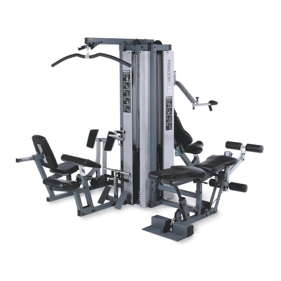
- Page 1 S3.45 Strength-Training Fitness Equipment Assembly and Maintenance Guide...
-
Page 2: Important Safety Instructions
Do not use accessory have damaged the equipment. attachments that are not recommended by the • Assemble and operate the S3.45 on a solid, level Serial number: _____________ manufacturer: such attachments might cause surface. Locate the unit a few feet from walls or injuries. -
Page 3: Table Of Contents
S3.45 Assembly and Maintenance Guide Table of Contents Important Safety Instructions ............... 2 Personal Safety During Assembly ................... 2 Obtaining Service ........................2 Before You Begin ................... 5 Unpacking the Equipment ....................... 5 Optional Equipment ......................... 5 Preparations ....................6 Required Tools ......................... - Page 4 S3.45 Assembly and Maintenance Guide Open Box 4 ..........................26 14. Attach Chest Press Seat ....................27 15. Attach Press Arm Assembly ..................28 16. Attach Handlebars ......................29 17. Assemble Chest Press Seat ..................30 18. Feed Chest Press Cable ....................31 Open Box 5 ..........................
-
Page 5: Before You Begin
S3.45 Assembly and Maintenance Guide Before You Begin Thank you for purchasing the S3.45. This unit is part of the Pacific Fitness line of quality strength-training machines, which let you target specific muscle groups to achieve better muscle tone and overall body conditioning. -
Page 6: Preparations
To find out the length of a particular bolt, measure • Set up the S3.45 on a solid, flat surface. A its shank (the long, narrow part beneath the head). CAUTION: To set up this unit, you will need... -
Page 7: Assembly Instructions
S3.45 by yourself. Review the Installation Requirements on page 6 before proceeding with the following steps. The S3.45 comes in four boxes. (See the diagram at the right.) Be careful to open boxes and assemble components in the sequence presented in this guide. -
Page 8: Open Boxes 1 And 2
S3.45 Assembly and Maintenance Guide Open Boxes 1 and 2 Use tie cutters to open the boxes. The illustration shows how the S3.45 will look after you complete this section. Note: Some items in these boxes may not be needed until later in the assembly process. -
Page 9: Attach Main Base
S3.45 Assembly and Maintenance Guide 1. Attach Main Base A. Place the Rear Upright on Weight Boxes with the flange side down. B. Place the Chest Press Rear Base on the Rear Upright. Balance the other end on a Weight Box. -
Page 10: Attach Top Beam And Top Frame
S3.45 Assembly and Maintenance Guide 2. Attach Top Beam and Top Frame Top Beam A. Place the Top Beam on the Rear Upright with windows facing down. Ensure the beam extends Top Frame out as shown. B. Place the Top Frame on the Rear Upright and Top Beam. -
Page 11: Attach Front Upright
S3.45 Assembly and Maintenance Guide 3. Attach Front Upright A. Attach the Front Upright to the Top Frame from the front using one 4¾-inch bolt two washers Top Frame one locknut Finger tighten. Note: Placement of the Front Upright must match the illustration. -
Page 12: Attach Cross Brace
S3.45 Assembly and Maintenance Guide 4. Attach Cross Brace A. Attach the Cross Brace to the Front Upright using two 3-inch bolts four washers Top Frame two locknuts B. Finger tighten. Do not wrench tighten until you attach the Seat Upright in step 5. -
Page 13: Open Box 3
S3.45 Assembly and Maintenance Guide Open Box 3 Use tie cutters to open the box. The diagram shows how the S3.45 will look after you complete this section. Note: Some items in these boxes may not be used until later in the assembly process. -
Page 14: Attach Seat Upright To Main Base
S3.45 Assembly and Maintenance Guide 5. Attach Seat Upright to Main Base Top Frame A. Attach the Seat Upright to the Main Base using two 4-inch bolts four washers two locknuts Finger tighten. Note: If the holes do not line up easily, tilt the main... -
Page 15: Attach Upright Flats
S3.45 Assembly and Maintenance Guide 6. Attach Upright Flats A. Attach the Rotating Arm to the Upright Flats using two ¾-inch buttonhead bolts 2 - ¾" buttonhead bolts Wrench tighten using the appropriate Allen wrench. B. Attach the Handles to the Seat Upright using two 3¼-inch bolts... -
Page 16: Attach Roller Pads
Roller Roller Rod. Pad Rod Note: If you are assembling the Leg Press Option and the S3.45 simultaneously, please go now to Step 2 in the S3.45 Leg Press Option Assembly Instructions. 2 - hex set screws Step 7. Attach Roller Pads... -
Page 17: Assemble Preacher Curl Weight Stack
8. Assemble Preacher Curl Top Frame Weight Stack Before assembling the Weight Stacks, be certain the S3.45 is positioned in its permanent location. 1 - 2¾" bolt A. Place two Guide Rods (from Box 1) into the large 2 - washers Retainer holes on the Preacher Curl side of the Main Base. -
Page 18: Assemble Leg Curl Weight Stack
S3.45 Assembly and Maintenance Guide 9. Assemble Leg Curl Weight Stack Top Frame A. Place two Guide Rods into the large holes on the Leg Curl side of the Main Base. B. Place one Weight Cushion on each Guide Rod and allow it to slide down to the top of the Main Base. -
Page 19: Assemble Chest Press Weight Stack
S3.45 Assembly and Maintenance Guide 10. Assemble Chest Press Weight Stack Top Frame A. Place two Guide Rods into the large holes on the Chest Press side of the Main Base. Use care not to get lubricant from the Rods on your clothing or on 1 - 2¾"... -
Page 20: Feed Lower Leg Curl Cable
S3.45 Assembly and Maintenance Guide 11. Feed Lower Leg Curl Cable A. Feed the barrel end of Cable 43622-103 under one 3½-inch pulley. Note the location of the Spring Clip in the illustration. Attach the pulley using two 2-inch bolts... - Page 21 S3.45 Assembly and Maintenance Guide E. Feed the barrel end of the Cable between the two Upright Flats. Attach the barrel end of the Cable to the Rotating Arm using Rotating Arm one 2¾-inch bolt two step spacers one locknut Pull all excess Cable between the Guide Rods toward the back of the Rear Base.
-
Page 22: Feed Upper Leg Curl Cable
S3.45 Assembly and Maintenance Guide 12. Feed Upper Leg Curl Cable A. Insert the Selector Stem (from Box 2) into the Leg Curl Weight Stack with the threaded hole at the top. Hold the Selector Stem with several holes Guide Rods above the Cap Plate. - Page 23 S3.45 Assembly and Maintenance Guide F. Attach two Floating Pulley Plates to one 4½-inch pulley using Cable from the Top one 2-inch bolt Frame two washers one locknut 1 - 4½" pulley Finger tighten. 1 - 2" bolt 2 - washers G.
-
Page 24: Assemble Leg Curl Seat
S3.45 Assembly and Maintenance Guide 13. Assemble Leg Curl Seat A. Attach the Backpad Support Tubes to the Seat Upright using Backpad Support one 5½-inch bolt Tubes two ½-inch washers one ½-inch locknut Note: The tube with the Selector Pivot Flat is nearest the Weight Stack. - Page 25 S3.45 Assembly and Maintenance Guide D. Attach the lower section of the Backpad to the lower hole of the right Backpad Support Tube using two 3-inch bolt two washers Finger tighten. Backpad Support Tubes E. Attach the Leg Curl Handle to the holes at the top of...
-
Page 26: Open Box 4
S3.45 Assembly and Maintenance Guide Open Box 4 Use tie cutters to open the box. The diagram shows how the S3.45 will look after you complete this section. Note: Some items in these boxes may not be needed until later in the assembly process. -
Page 27: Attach Chest Press Seat
S3.45 Assembly and Maintenance Guide 14. Attach Chest Press Seat A. Attach the Chest Press Upright to the Chest Press Seat using four ¾-inch bolts four washers Finger tighten. B. Attach the lower hole at top of the Chest Press... -
Page 28: Attach Press Arm Assembly
S3.45 Assembly and Maintenance Guide 15. Attach Press Arm Assembly CAUTION: This step requires two people. Do not pinch yourself between the Press Arm and the Prestretch Tube. 2 - 4" bolts 4 - washers A. Attach the Press Arm Assembly to the Rear Upright... -
Page 29: Attach Handlebars
S3.45 Assembly and Maintenance Guide 16. Attach Handlebars A. Slide each Handlebar (one at a time) onto the Pivot Shaft and attach it using one ½-inch washer one ½-inch hat washer Press Arm one locknut Assembly Note: Tighten the locknut until the Handlebars don't move. -
Page 30: Assemble Chest Press Seat
S3.45 Assembly and Maintenance Guide 17. Assemble Chest Press Seat A. Place the Backpad and Headrest on the floor. Place Long Support Tube the Long Support Tube and Short Support Tube on 2 - 1¼" bolts 3 - 3" bolts... -
Page 31: Feed Chest Press Cable
S3.45 Assembly and Maintenance Guide 18. Feed Chest Press Cable Ensure the Cable passes between the pulley and This completes box 4. You may move the box out of retainer pin. Wrench tighten. the way. A. Insert the Selector Stem into the Chest Press E. - Page 32 S3.45 Assembly and Maintenance Guide 1 - 4½" pulley 1 - 2¾" bolt 2 - ½" step spacers 1 - locknut Guide Rods 1 - 6" pulley 1 - 2¾" bolt Cap Plate 2 - ½" step spacers 1 - locknut 1 - 1½"...
-
Page 33: Open Box 5
S3.45 Assembly and Maintenance Guide Open Box 5 Use tie cutters to open the box. The diagram shows how the S3.45 will look after you complete this section. Note: Some items in these boxes may not be used until later in the assembly process. -
Page 34: Attach Foot Support
S3.45 Assembly and Maintenance Guide 19. Attach Foot Support A. Attach the Foot Support to the Preacher Curl Rear Base using two 3¼-inch bolts four washers two locknuts Wrench tighten. Foot Support 2 - 3¼" bolts 4 - washers 2 - locknuts Step 19. -
Page 35: Attach Seat Frame
S3.45 Assembly and Maintenance Guide 20. Attach Seat Frame A. Attach the Seat Frame to the Preacher Curl Rear Base using two 3¼-inch bolts four washers two locknuts Wrench tighten. Seat Frame 2 - 3¼" bolts 4 - washers 2 - locknuts Step 20. -
Page 36: Attach Row Bar Shelf And Seat Pads
S3.45 Assembly and Maintenance Guide 21. Attach Row Bar Shelf and Seat Pads Arm Pad A. Attach the Row Bar Shelf to the Rear Upright above the pulley window using one 3¾-inch bolt 1 - 3¾" bolt two washers 2 - washers... -
Page 37: Feed Upper Preacher Curl Cable
S3.45 Assembly and Maintenance Guide 22. Feed Upper Preacher Curl Cable A. While standing on a step ladder, feed the U end of Cable 43621-103 through the window in the Top 1 - 2¾" bolt Beam and out the window at the other end. Note the 2 - washers location of the Spring Clip on the Cable. - Page 38 S3.45 Assembly and Maintenance Guide F. Ensure the U end of the Cable feeds between the Guide Rods. Insert the Selector Stem into the Preacher Curl Weight Stack with the threaded hole at the top. Hold the Selector Stem with several holes above the Cap Plate.
-
Page 39: Feed Lower Preacher Curl Cable
S3.45 Assembly and Maintenance Guide 23. Feed Lower Preacher Curl Cable A. Wrap the center of Cable 43620-103 around one 4½- inch pulley and attach it in the remaining hole of the two Floating Pulley Plates using Step 22 one 2-inch bolt... - Page 40 Press Station until you feel the Weight Stack begin to lift. Wrench tighten the pulley in that position. Note: If you are assembling the Leg Press Option and the S3.45 simultaneously, go to Step 5 in the S3.45 Leg Press Option Assembly Instructions now. Rear Upright Step 23.
-
Page 41: Attach Lat Bar Holders
S3.45 Assembly and Maintenance Guide 24. Attach Lat Bar Holders A. Attach the Lat Bar Holders to the Top Beam using two 3¼-inch bolts four washers two locknuts B. Wrench tighten. Top Beam 2 - 3¼" bolts 4 - washers... -
Page 42: Attach Accessories
S3.45 Assembly and Maintenance Guide 25. Attach Accessories A. Attach the Lat Bar to the Spring Clip at the end of the Top Beam. B. Attach the Row (V) Handle to the Spring Clip at the upper window of the Rear Upright and place it in the holder above it. -
Page 43: 26. Apply Weight Decals
S3.45 Assembly and Maintenance Guide 26. Apply Weight Decals A. Remove the backing for the decals labeled “1–5.” Press the decals to the front surface of the top five weight plates in the tab location as indicated. Remove the front decal protector. -
Page 44: Open Box 6
S3.45 Assembly and Maintenance Guide Open Box 6 Use tie cutters to open the box. The illustration shows how the S3.45 will look after you complete this section. Open Box 6 page 44... -
Page 45: Attach Shrouds
S3.45 Assembly and Maintenance Guide 27. Attach Shrouds 1 - 3¾" buttonhead bolt Important: Before attaching the Shrouds, make any 1 - 3" barrel spacer necessary adjustments. Refer to "Adjustments and Maintenance" on page 47. A. Slide the Left-Hand Leg Curl Shroud between the Front Upright and the Main Base, starting from the 1 - 2¾"... - Page 46 ¼-inch by 2½-inch buttonhead bolts. Wrench tighten all bolts, for steps A through E. 1 - 3¾" buttonhead bolt This completes the assembly of your Precor S3.45. 1 - 3" barrel spacer Side Shroud Side Shroud 1 - 3¾" buttonhead bolt 1 - 3"...
-
Page 47: Adjustments And Maintenance
Adjustments and Maintenance Top Cap Weight After the S3.45 is completely assembled, you must check the Cables for proper tension. Obvious signs that Cable problems exist include: ✔ The Cap Plate does not rest squarely on the top Top Weight weight of the Weight Stack. -
Page 48: Selector Stem Adjustments
U Bracket A. Remove the Weight Pin from the Weight Stack. B. Perform an exercise using each part of the S3.45. When the base of the Selector Stem is clear of the Weight Stack, observe the position of the 1 ½"... -
Page 49: Backward Angle Adjustment
S3.45 Assembly and Maintenance Guide D. Reassemble the Cap Plate, Selector Stem, and Cable Clamp. E. Test the movement of the Selector Stem inside the Weight Stack. Backward Angle Adjustment If the Selector Stem continues to contact the plates, repeat steps A through E until the Selector... -
Page 50: Side-To-Side Vertical Adjustment
S3.45 Assembly and Maintenance Guide Side-to-Side Vertical Adjustment If the Selector Stem contacts the inside of the Weight Pull the Selector Stem and Stack during use or the Weight Pin becomes difficult to Top Cap Weight up to insert in the Weight Stack, the Selector Stem may be expose at least 5 holes. - Page 51 page 51...
- Page 52 page 52 Please detach and mail in the warranty registration within ten days of purchase.
-
Page 53: Precor Residential Equipment Limited Warranty
Satisfactory proof of purchase is required in all cases. For any product described above that fails to conform to its warranty, Precor will provide, at their option, one of the following: (1) repair; (2) replacement; or (3) refund of the purchase price. Precor Limited Warranty service Conditions and Restrictions may be obtained by contacting the authorized dealer from whom you purchased the item. -
Page 54: Warranty Registration
Precor is widely recognized for its innovative, award winning designs of exercise equipment. Precor aggressively seeks U.S. and foreign patents for Warranty Registration # 45623-102 both the mechanical construction and the visual aspects of its product design. Any party contemplating the use of Precor’s product designs is hereby Warranty Card # 36287-110 forewarned that Precor considers the unauthorized appropriation of its proprietary rights to be a very serious matter.
Need help?
Do you have a question about the move beyond S3.45 and is the answer not in the manual?
Questions and answers