Table of Contents
Advertisement
Quick Links
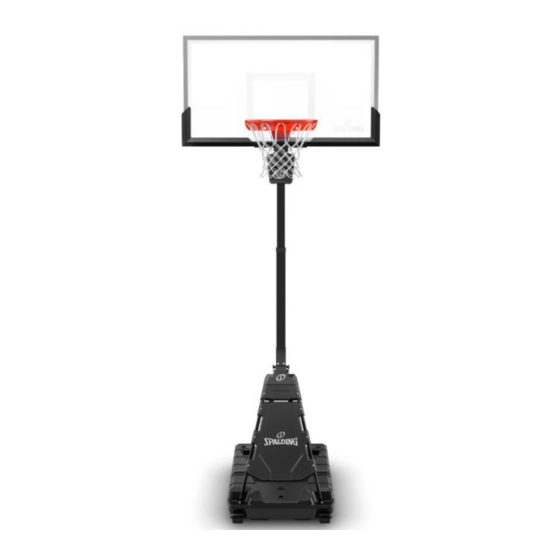
PORTABLE BASKETBALL SYSTEM
Toll-Free Customer Service Number
U.S.:
1-800-558-5234
Canada:
1-800-284-8339
Europe:
+353 51 379777
Australia: 1300 367 582
www.spalding.com
WARNING
READ AND UNDERSTAND THE OPERATOR'S
MANUAL BEFORE USING THIS UNIT.
FAILURE TO FOLLOW THE OPERATING
INSTRUCTIONS COULD RESULT IN INJURY
OR DAMAGE TO PROPERTY.
Owner's Manual
Model Number:
(found on product box)
4/21 ID# M6E11E00
Advertisement
Table of Contents

Subscribe to Our Youtube Channel
Related Manuals for SPALDING SPA0366


Summary of Contents for SPALDING SPA0366
- Page 1 U.S.: 1-800-558-5234 Canada: 1-800-284-8339 Europe: +353 51 379777 Australia: 1300 367 582 www.spalding.com WARNING READ AND UNDERSTAND THE OPERATOR’S MANUAL BEFORE USING THIS UNIT. FAILURE TO FOLLOW THE OPERATING INSTRUCTIONS COULD RESULT IN INJURY OR DAMAGE TO PROPERTY. 4/21 ID# M6E11E00...
-
Page 2: Table Of Contents
Questions or missing parts? Do NOT go back to the store! Email: warrantyservice@custserv.fotlinc.com Customer Service 1-800-558-5234 Toll-Free Number: Mailing Address: Spalding PO Box 90015 Bowling Green, KY 42102 Warranty For the very latest Basketball System Warranty information, please visit www.Spalding.com or call Spalding Customer Service at 1-800-558-5234. -
Page 3: Safety Information
Safety Information Safety Information WARNING FAILURE TO FOLLOW THESE SAFETY INSTRUCTIONS MAY RESULT IN SERIOUS INJURY OR PROPERTY DAMAGE AND WILL VOID THE WARRANTY. Owner must ensure all players know and follow these rules for safe operation of the system. To ensure safety, do not attempt to assemble this system without following the instructions carefully. -
Page 4: Package Contents
Package Contents Package Contents Check the contents of each kit and other parts to ensure that all components are present. Keep the kit hardware in the labeled bag as they will be used in different assembly steps. See "Parts List" on page 23 for a complete list of replacement part numbers. PRIMARY ASSEMBLY COMPONENTS Primary Sub-Assembly (x1) Extension Arm (x1) - Page 5 Package Contents KIT 2 – 209221 203100 NUT, HEX FLANGE, 5/16-18 10 Bolt, Hex, Flange, 5/16-18 x 1" (x4) 11 Nut, Wiz, 5/16-18 (x4) 12 T-Bolt (x1) KIT 3 – 209242 13 Spring (x1) 14 Nut, Special (x1) 15 Washer, Flat, 1.5" OD (x1) 16 Bracket, Reinforcement (x1) 17 Screw, 1/4 x 0.375"...
-
Page 6: Tools & Materials For Assembly
Tools & Materials for Assembly KIT 5 – 209224 208505 23 Bolt, Carriage, 1/4-20 x 1.5" (x8) 24 Knob, 1/4-20 (x8) 25 Thumbscrew, M8 x 1.25 (x2) KIT 6 – 209225 26 Handle Assembly (x1) 27 Pull Pin, Handle (x1) Tools &... -
Page 7: Assembly Overview
Assembly Overview Assembly Overview Backboard (Section B, C) Extension Arm Cover (Section H) Rim (Section D) Crank Handle (Section G) Pole (Section E) Base (Section A) Front Cover (Section F) -
Page 8: Fill The Base
Fill the Base Fill the Base Required Parts: Completed Base Assembly: • SAND/GARDEN HOSE FILL THE BASE 1. Roll the primary sub-assembly to the desired location for use. 2. Fill the base with water (approx. 36 gallons (136 Liters)) or sand (approx. -
Page 9: Assemble The Extension Arm
Assemble the Extension Arm Assemble the Extension Arm Required Parts: Completed Base Assembly: • KIT 1 • WRENCHES AND/OR SOCKET WRENCHES (9/16") INSTALL THE EXTENSION ARM 1. Attach the extension arm (2) to the middle pole using the hex bolts (8). 2. -
Page 10: Assemble The Backboard
Assemble the Backboard Assemble the Backboard Required Parts: Completed Goal Assembly: • KIT 2 • WRENCHES AND/OR SOCKET WRENCHES (1/2") IMPORTANT CAREFULLY CUT AND PEEL PROTECTIVE FILM AWAY FROM BOARD PRIOR TO ATTACHING RIM. INSTALL THE BACKBOARD 1. Insert the t-bolt (12) through the rim bracket (9). 2. -
Page 11: Assemble The Rim
Assemble the Rim Assemble the Rim Required Parts: Completed Goal Assembly: • KIT 3 • WRENCHES AND/OR SOCKET WRENCHES (3/4") • PHILLIPS SCREWDRIVER ASSEMBLE THE GOAL 1. Fit the rim (4) securely into the rim bracket (9). Allow the t-bolt (12) to slip through the center hole in the rim (4). - Page 12 Assemble the Rim ASSEMBLE THE GOAL 3. Install the spring (13) onto the t-bolt (12). 4. Install the special nut (14) and washer (15) onto the t-bolt (12). 5. Tighten the nut (14) until 1/8" of the bolt threads onto the exposed end of the t-bolt (12). 1/8"...
- Page 13 Assemble the Rim ASSEMBLE THE GOAL 6. Attach the cover (5) to the rim (4) using the cover screws (17).
-
Page 14: Assemble The Upright
Assemble the Upright Assemble the Upright Required Parts: Completed Pole Assembly: • KIT 4 • WRENCHES AND/OR SOCKET WRENCHES (1/2"; 3/4") WARNING TWO PEOPLE ARE REQUIRED FOR THIS PROCEDURE. FAILURE TO FOLLOW THIS WARNING COULD RESULT IN SERIOUS INJURY AND/OR PROPERTY DAMAGE. - Page 15 Assemble the Upright ASSEMBLE THE POLE STRUTS 1. From the front of the unit, rotate the pole assembly upward. A second person must support the backboard (3). 18" IMPORTANT DURING STEPS 1-2, THE SECOND PERSON SUPPORTING BACKBOARD ONLY NEEDS TO LIFT TOP EDGE OF THE BACKBOARD APPROXIMATELY 18"...
- Page 16 Assemble the Upright ASSEMBLE THE POLE STRUTS 4. Attach the extension arm cover (31) to the extension arm using screws (32) and washers (30). NOTE The top edge of the backboard should rest on the ground for this assembly. WARNING •...
- Page 17 Assemble the Upright ASSEMBLE THE POLE STRUTS 7. Insert the hex bolt (21) and secure with the nut (22). Tighten completely. IMPORTANT YOU MAY NEED TO SLIGHTLY ADJUST POSITION OF PRIMARY UPRIGHT TO ACHIEVE PROPER HOLE ALIGNMENT FOR BOLT INSERTION. GENTLY PUSH THE UPRIGHT BACK AND FORTH UNTIL PROPER CLEARANCE FOR BOLT INSERTION IS ACHIEVED.
-
Page 18: Assemble The Front Cover
Assemble the Front Cover Assemble the Front Cover Required Parts: Completed Goal Assembly: • KIT 5 IMPORTANT ENSURE ALL CARRIAGE BOLTS ARE INSERTED PRIOR TO TIGHTENING COMPLETELY. ASSEMBLE THE FRONT COVER 1. Attach the front cover (6) to the struts using carriage bolts (23) and tri-knobs (24). - Page 19 Assemble the Front Cover ASSEMBLE THE FRONT COVER 2. Attach the knuckle shroud (7) using the carriage bolts (23), tri-knobs (24), and thumbscrews (25). IMPORTANT ENSURE ALL CARRIAGE BOLTS AND THUMBSCREWS ARE INSERTED PRIOR TO TIGHTENING COMPLETELY.
-
Page 20: Assemble The Handle Assembly
Assemble the Handle Assembly Assemble the Handle Assembly Required Parts: Completed Goal Assembly: • KIT 6 INSTALL THE HANDLE ASSEMBLY 1. Attach the crank handle assembly (26) and pull pin (27). - Page 21 Assemble the Handle Assembly INSTALL THE HANDLE ASSEMBLY 2. Apply the Height Adjustment and Moving Label (29) to the front of the pole, where it is clearly visible. HEIGHT ADJUSTMENT MOVING SYSTEM 1. While holding pole, rotate basketball sytem forward until wheels engage with ground. 2.
-
Page 22: Operation
Operation Operation ADJUSTING THE HEIGHT WARNING DO NOT ALLOW CHILDREN TO ADJUST THE HEIGHT. 1. Insert the pull pin (27). 2. Crank the handle (26) to adjust up or down to the desired height. 3. Replace the pull pin (27) to lock in place. MOVING THE UNIT 1. -
Page 23: Parts List
Parts List Parts List... - Page 24 Parts List Item Part No . Description Item Part No . Description 801800 Primary Sub-Assembly 204558 Screw, 1/4 x 0.375" Long 901837 Extension Arm 203218 Washer, .375" ID Backboard Assembly 209185 Nut, Acorn, Locking, 5/16-18 209112 Pull Pin 908355 Rim Cover, Orange 206273 Bolt, Hex, 1/2-13 x 4.5"...
- Page 26 APPELEZ LE NUMÉRO SANS FRAIS : • DO NOT slide, climb, shake, or play on 1.800.558.5234 | www.hu ysports.com base and/or pole. www.spalding.com • After full assembly, fill system completely with water or sand. Never leave system in an upright position...
Need help?
Do you have a question about the SPA0366 and is the answer not in the manual?
Questions and answers