Table of Contents
Advertisement
Quick Links
Advertisement
Table of Contents

Related Manuals for GF GF 500


Summary of Contents for GF GF 500
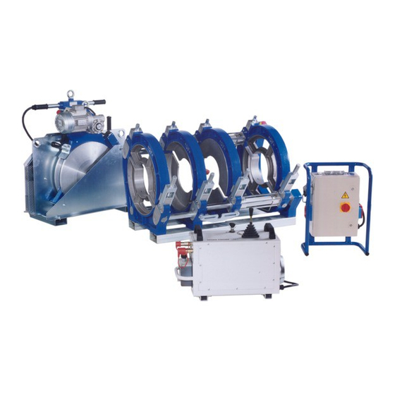
- Page 1 GF 500 Butt Fusion Machine Operating Instructions...
- Page 2 All rights reserved, in particular the rights of duplication and distribution as well as translation. Duplication and reproduction in any form (print, photocopy, microfilm or electronic) require the written permission of Georg Fischer Omicron S.r.l..
-
Page 3: Table Of Contents
Operating instructions GF 500 Table of contents Table of contents Page About this manual Warning notice Other symbols and notices Abbreviations Safety instructions Proper use General safety measures Working with safety in mind Disposal Further safety guidelines Other disposal General... - Page 4 Table of contents Operating instructions GF 500 Replacement of worn parts Hydraulic system Hydraulic unit 10 Customer Service...
-
Page 5: About This Manual
Operating instructions GF 500 0 About this manual About this manual The warning notices, symbols and their meanings as used in this manual are explained below to help you quickly understand the format of this instruction manual and how to use the machine safely. -
Page 6: Other Symbols And Notices
0 About this manual Operating instructions GF 500 Other symbols and notices Symbol Meaning Important This notice contains especially important information. Attention Mandatory: you must observe this regulation. Call for action in a particular sequence. You must do something here. -
Page 7: Safety Instructions
Complete documentation should be kept in the vicinity of the • machine. Proper use The GF 500 is to be used exclusively for the fusion of pipes and fittings made of PE, PP and PVDF. General safety measures Use only the materials and dimensions specified in this manual. Other •... -
Page 8: Working With Safety In Mind
• For your own personal safety as well as for the safe and optimal handling of the machine, the GF 500 must be installed correctly. Connect hydraulic hoses to and from the machine only when the hydraulic unit is shut off and not under pressure (observe manometer). -
Page 9: Disposal
Operating instructions GF 500 1 Safety instructions Disposal Shavings and used hydraulic oil should be disposed of properly. Further safety guidelines Observe all the regulations, standards and guidelines applicable in your country. Other disposal Separate collection of electronic and electrical waste (from the equipment) has to be ensured through appropriate systems. -
Page 10: General
General Introduction This instruction manual was written for those persons responsible for the operation and care of the GF 500. It is expected and assumed that such persons have read, understood and will abide by the manual in its entirety. -
Page 11: Copyright
Operating instructions GF 500 2 General Copyright copyright this instruction manual held Georg Fischer Omicron S.r.l.. This instruction manual is intended for assembly, operation and maintenance personnel. No part of the technical regulations or illustrations contained herein may be reproduced or distributed in any form, used illicitly for competitive purposes or passed on to others. -
Page 12: Product Design, Equipment
3 Product design, equipment Operating instructions GF 500 Product design, equipment Design Storage case with heater and planer Basic machine Hydraulic unit 4 Power control box... -
Page 13: Standard Equipment
Operating instructions GF 500 3 Product design, equipment Standard equipment • Base machine Hardened and hard chrome-plated guide shafts – 2. clamping element relocatable – Heater release mechanism to optimize the changeover phase – Tool and wrench set – •... -
Page 14: Technical Specifications
4 Technical specifications Operating instructions GF 500 Technical specifications Planer Power: Electromotor 760 W Voltage: 400 V Heater Power: 4000 W Voltage: 400 V Hydraulic unit Power: 1500 W Voltage: 400 V Viscosity 46 Oil type: 2 liters of hydraulic oil in canister, Code No. -
Page 15: Transport And Assembly
Normally, the machine and all the accessories are delivered in a cardboard box on a pallet. Sensitivity Special care must be taken when transporting the GF 500 in order to prevent damage from impact or improper loading and unloading. All movable parts must be fixed in place. -
Page 16: Fusion Preparation
For optimal use of the GF 500, operating personnel should be specially trained by Georg Fischer. In-depth knowledge of the machine and it´s components and competence rule out handling errors thereby also preventing faulty fusion joints. -
Page 17: Fusion
Operating instructions GF 500 7 Fusion Fusion The basics of butt fusion For butt fusion with a heating element, the parts to be joined (pipe/pipe, pipe/fitting fitting/fitting) heated fusion temperature in the fusion area and are fused under pressure without the use of additional materials. -
Page 18: The Fusion Process
7 Fusion Operating instructions GF 500 The fusion process In order to weld pipes and/or fittings d < 500 mm, insert matching clamping half shells and fasten them with the screws. Clamp pipe/pipe, pipe/fitting or fitting/fitting in the clamping 4 cm 4 cm element. -
Page 19: Adjusting Of The Fusion Pressure
Operating instructions GF 500 7 Fusion 7.2.3 Adjusting of the fusion pressure 1. Open the machine. 2. Reduce pressure with the fine-adjustment pressure valve (turn counter-clockwise). 3. Move control lever towards “close ><” position and increase pressure on the pressure valve (turn clockwise) until clamping carriage moves smoothly. -
Page 20: Fusion Process
7 Fusion Operating instructions GF 500 Caution Constant high pressure when facing, can cause damage on the drive and/or the motor of the facer. 4. Plane the facing surface of pipes/fittings until shavings are turned out in ribbons which are the same width as the pipe wall thickness. The max. - Page 21 Operating instructions GF 500 7 Fusion For fusion parameters, see Chapter 7.5. Equalization (fusion bead created on both sides) 1. Insert Heater into “pull off” device. 2. Move the parts to be joined together, push the control lever in the “close ><”...
-
Page 22: Visual Check Of Welding Bead
7 Fusion Operating instructions GF 500 Joining (Fusion process) Push joystick in “close ><“ position until pipes touch each other and the preset fusion pressure is reached. Hold this position for 15 sec. Then slowly return the joystick in to 0-position. -
Page 23: Example
Operating instructions GF 500 7 Fusion Example Pipe/fitting Heater temperature 210 °C Pipe outer diameter 400 mm Drag resistance 7 bar Pressure rating SDR 11 Table value 44 bar Wall thickness 36.3 mm Adjustment value on 51 bar hydraulic unit Equalize with a pressure of 51 bar until a bead height of 3.0 mm... - Page 24 7 Fusion Operating instructions GF 500 Curve standard values heater temperatures relation to pipe wall thickness Process steps heating element butt fusion Heating element butt fusion of HD-PE Time/Pressure tables according to DVS 2207/1 Pipe outer diameter Wall thickness 11.0 12.3...
- Page 25 Operating instructions GF 500 7 Fusion Heating element butt fusion of HD-PE Time/Pressure tables according to DVS 2207/1 Pipe outer diameter Wall thickness 10.7 12.1 13.6 15.3 17.2 19.1 Fusion surface mm² 4652 5847 7250 9053 11514 14587 18491 23387...
- Page 26 7 Fusion Operating instructions GF 500 Heating element butt fusion of HD-PE Time/Pressure tables according to DVS 2207/1 Pipe outer diameter Wall thickness 11.4 12.8 14.2 15.9 17.9 20.1 22.7 25.5 28.4 Fusion surface mm² 6755 8533 10519 13192 16707...
- Page 27 Operating instructions GF 500 7 Fusion Heating element butt fusion of HD-PE Time/Pressure tables according to DVS 2207/1 Pipe outer diameter Wall thickness 18.2 20.5 22.7 25.4 28.6 32.2 36.3 40.9 45.4 Fusion surface mm² 10395 13170 16210 20316 25733...
- Page 28 7 Fusion Operating instructions GF 500 Heating element butt fusion of PP Fusion table/DVS 2207/11 guidelines Heating element temperature 210 °C ± 10 °C Nominal wall Equalize Heat soak Change-over Join Cooling thickness Bead height on the (heat soak Time until max...
- Page 29 Operating instructions GF 500 7 Fusion Heating element butt fusion of PP Time/Pressure tables according to DVS 2207/11 Pipe outer diameter Wall thickness 11.0 12.3 Fusion surface mm² 3003 3793 4749 5920 7434 9465 12013 15171 18846 Equalization/fusion pressure bar...
- Page 30 7 Fusion Operating instructions GF 500 Heating element butt fusion of PP Time/Pressure tables according to DVS 2207/11 Pipe outer diameter Wall thickness 18.2 20.5 22.7 25.4 28.6 32.2 36.3 40.9 45,5 Fusion surface mm² 10395 13170 16210 20316 25733...
-
Page 31: Failure Analysis
Operating instructions GF 500 8 Failure analysis Failure analysis 1. On cracks parallel to or across the fusion joint, check: in the joint – in the heat flow zone – in the basic material – 2. Bead notches traversing or local notches parallel to the joint with their... - Page 32 8 Failure analysis Operating instructions GF 500 9. Jointing error on the fusion surfaces, over the entire or part of the joint circumference due to dirty and/or oxidized fusion surfaces – change-over time too long – heater temperature too high/too low –...
-
Page 33: Maintenance
Operating instructions GF 500 9 Maintenance Maintenance The GF 500 should be checked and cleaned periodically. Normal care of the GF 500 is limited to periodic cleaning of the outside. Replacement of worn parts • PTFE coating of the heating element:... - Page 34 2. Pour in 2 liters of new hydraulic oil. Oil filler neck Dispose of used, dirty oil properly. Attention We recommend having a service booklet to record maintenance work Service booklet for each GF 500 machine. Example: Date Service Repair Comments 15.09.2000...
- Page 35 Operating instructions GF 500 10 Customer Service 10 Customer Service There is a separate spare part list for ordering replacement parts. If repairs are necessary, please contact your local representative. Please indicate the following information: Machine type GF 500 •...
- Page 36 GF 500_english_rev01.doc Code no.: ALIBR74201-A Georg Fischer Omicron S.r.l. Via Enrico Fermi, 12 I 35030 Caselle di Selvazzano (Padova) – Italy...
Need help?
Do you have a question about the GF 500 and is the answer not in the manual?
Questions and answers