
Related Manuals for Matrix PL218


Summary of Contents for Matrix PL218
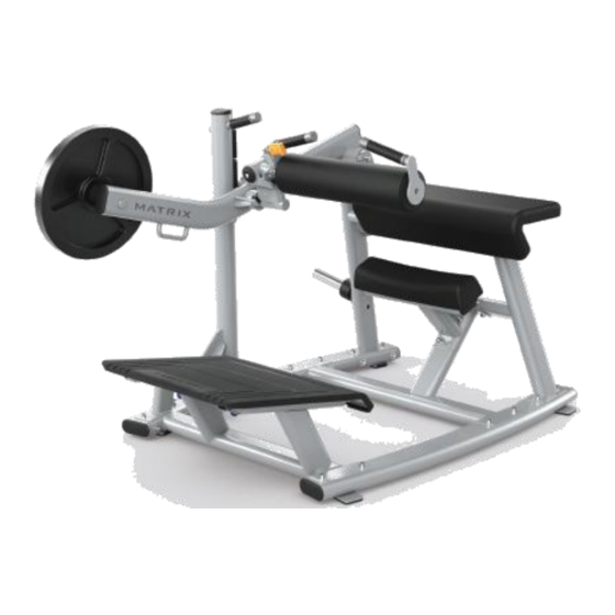
- Page 1 Issue date Edition Doc No. JOHNSON Revision Edition time Page date PL218 GLUTE TRAINER SERVICE MANUAL Approval Review Editor Hans Kong...
-
Page 2: Table Of Contents
CONTENTS CHAPTER 1:SERIAL NUMBER LOCATION...................1 CHAPTER 2:MAINTENANCE & SAFETY....................2 CHAPTER 3: ASSEMBLY INSTRUCTION....................4 CHAPTER 4:TROUBLESHOOTING......................7 4.1 Pedal Arm Stuck..........................7 4.2 Link Arm Stuck..........................8 4.3 Adjustable Pin Stuck........................9 CHAPTER 5:PARTS REPLACEMENT....................10 5.1 Bushing............................10 5.2 Handlebar............................11 5.3 Adjustment Set..........................12... -
Page 3: Chapter 1:Serial Number Location
CHAPTER 1:SERIAL NUMBER LOCATION... -
Page 4: Chapter 2:Maintenance & Safety
CHAPTER 2:MAINTENANCE & SAFETY IMPORTANT SAFETY INFORMATION It is the sole responsibility of the purchaser of MATRIX products to instruct all individuals, whether they are the end user or supervising personnel on proper usage of the equipment. It is recommended that all users of MATRIX exercise equipment be informed of the following information prior to its use. - Page 5 CHAPTER 2:MAINTENANCE & SAFETY PROPER USAGE 1. Do not exceed weight limits of the exercise device. 2. If applicable, set safety stops to appropriate height. 3. If applicable, adjust seat pads, leg pads, foot pads, range of motion adjustment, or any other type of adjustment mechanisms to a comfortable start position.
-
Page 6: Chapter 3: Assembly Instruction
CHAPTER 3: ASSEMBLY INSTRUCTION... - Page 7 CHAPTER 3: ASSEMBLY INSTRUCTION...
- Page 8 CHAPTER 3: ASSEMBLY INSTRUCTION...
-
Page 9: Chapter 4:Troubleshooting
CHAPTER 4:TROUBLESHOOTING 4.1 Pedal Arm Stuck 1. Remove the screw on the bottom of pedal arm (Figure A). 2. Pull out the arm as shown by the direction of the arrows (Figure B). 3. Check whether the pin is rough or broken. If it is, install a new one (Figure C). Figure A Figure B Figure C... -
Page 10: Link Arm Stuck
CHAPTER 4:TROUBLESHOOTING 4.2 Link Arm Stuck 1. Remove the screw and C-ring in the link arm (Figure A & B). 2. Remove 2 screws in the front (Figure C). 3. Remove the axle and see if it’s rough or broken (Figure D). Figure A Figure B Figure C... -
Page 11: Adjustable Pin Stuck
CHAPTER 4:TROUBLESHOOTING 4.3 Adjustable Pin Stuck 1. Remove the fixing block and the chain. 2. Remove the adjustable pin and check if it’s rough or broken. Figure A Figure B PS: You must also apply Super Lube grease to the axle. -
Page 12: Chapter 5:Parts Replacement
CHAPTER 5:PARTS REPLACEMENT 5.1 Bushing 1. Remove 4 screws locking the block. (Figure A) 2. Remove stopper block, washer, bousing one by one for each bar. (Figure B&C&D) 3. Reverse step 2-1 to restore. Figure A Figure B Figure C Figure D... -
Page 13: Handlebar
CHAPTER 5:PARTS REPLACEMENT 5.2 Handlebar 1. For first type handle, remove the screws on end cup and block. (Figure A) 2. For second type handle, remove the rubber block and screws. (Figure B) 3. For third type handle, remove block&screw then tube can be removed. (Figure C) 4. -
Page 14: Adjustment Set
CHAPTER 5:PARTS REPLACEMENT 5.3 Adjustment Set 1. Remove the round pad; it is fixed by cap and screw. (Figure A&B) 2. Remove the adjustable pin as shown in section 4.3. 3. Remove 2 screws (on each side) then take off sheaths and plates one by one. (Figure C) 4.
Need help?
Do you have a question about the PL218 and is the answer not in the manual?
Questions and answers