Table of Contents
Advertisement
Quick Links
Advertisement
Table of Contents

Related Manuals for Renishaw MP7


Summary of Contents for Renishaw MP7
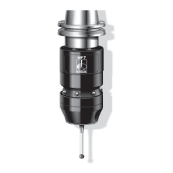
- Page 1 Installation and user’s guide H-2000-5085-02-I MP7 - MP8 - MP9 probe systems...
- Page 2 © 2003 - 2004 Renishaw. All rights reserved. Disclaimer This document may not be copied or Considerable effort has been made to reproduced in whole or in part, or transferred ensure that the contents of this document to any other media or language, by any are free from inaccuracies and omissions.
- Page 3 Installation and user's guide MP7 - MP8 - MP9 probe systems...
- Page 4 FCC Section 15.21 This device complies with Part 15 of the FCC The user is cautioned that any changes or rules. modifications not expressly approved by Renishaw Operation is subject to the following two plc, or authorised representative could void the conditions: user's authority to operate the equipment.
- Page 5 MP9 probes rattles when the probe body is PATENT NOTICE shaken. This is quite normal and should not be Features of MP7-8-9 probes and features of similar the cause of any concern. probes are the subjects of the following patents and or patent applications.
-
Page 6: Table Of Contents
MP7 - 8 - 9 stylus spring pressure FAULT FINDING ........35 adjustment ..........16 APPENDIX 1 Adaptor and MP7 - 8 - 9 battery covers and battery .. 17 Extensions ..........38 MP7 - 8 - 9 stylus on-centre adjustment APPENDIX 2 power supply using adjustment plate ...... -
Page 7: Typical Probe Systems
Mounting bracket Machine spindle OMI (one only) Optional - PSU3 + CNC control power supply unit Shank (size 25 - 50) (one or two) MP7 - 8 - 9 machine + MI 12 Battery inspection control + CNC control cover probe... -
Page 8: Two Omms And Remote Indicator
TWO OMMs and REMOTE INDICATOR OMM TANDEM MOUNTING OMM 1 Installations with exceptionally long spindle travel, may require a second OMM to cover signal reception over the full working envelope of the probe. The reception cones of OMM 1 and OMM 2 overlap, so they Spindle act as one receiver. -
Page 9: System Performance
SYSTEM PERFORMANCE OPERATING ENVELOPE PROBE REPEATABILITY Maximum 2 sigma (2σ σ σ σ σ ) value Natural reflective surfaces within the machine may increase the signal transmission range. Repeatability of 1.0 µm (40 µin) is valid for Coolant residue accumulating on the OMP diodes test velocity of 480 mm/min (1.57 ft/min) at and OMM or OMI window, will have a detrimental stylus tip, using stylus 50 mm (1.97 in) long. -
Page 10: Operating Envelope
OPERATING ENVELOPE for MP7 - 8 - 9 PROBES with 35° or 70° OUTPUT 35° 70° Optical centre line OMM ±20° Spindle travel Beams must always overlap OMM ±10° ±25° ±20° OMI ±15° OMM ±15° OMP ±10° OMI ±20°... -
Page 11: Probe Features
PROBE FEATURES MP7 - MP9 On-centre adjusting plate Shank translation Ø8 mm ball screw adjusters (optional) Battery Shank cover Shank switch Battery cover seal Battery (Optical module probe) 7 x transmit LED (Tx) Enhanced trigger circuit Stylus spring pressure adjustment... -
Page 12: Mp7 - 9 With Centre Ball Adjustment
MP7 - 9 with CENTRE BALL ADJUSTMENT dimensions mm (in) TO FIT SHANK 1. Remove battery covers and battery. 2. Remove adjusting plate. 3. Fit shank and centre ball to probe. 4. Set stylus on-centre position - see page 20. -
Page 13: Mp7 - 9 With Adjusting Plate
MP7 - 9 with ADJUSTING PLATE dimensions mm (in) TO FIT SHANK 1. Remove battery covers and battery. 2. Fit shank to probe. 3. Set stylus on-centre position - see page 19. 4. Replace battery and covers. Disc washer Socket head screw... -
Page 14: Mp7 - 9 With Adjusting Plate And Taper Shank
3 (1.12) ❃ Two holes GAUGE LINE ❃ M4 x 0.7 x 10 deep 7 (0.27) Shanks available from Renishaw - Please quote the Part No. when ordering equipment Shank Part No. Taper DIN 69871 M-2033-6637 50 (1.969) 19.1 - 19.0 (0.752 - 0.748) M-2033-6636 50 (1.969) -
Page 15: Mp8 With Adjusting Plate And Taper Shank
Ø62 70° (2.44) Ø48 Adjusting (0.87) 7.13 (0.28) (Ø1.89) plate Pull stud Ø14.25 (Ø.56) 35° (Not supplied by Renishaw) 17.5° 17.5° Ø6 (0.24) Typical 21.5 Stylus taper shank 50 (1.97) long. (0.85) Other length styli may be used. Dimension 63.0 (2.48) -
Page 16: Mp8 Probe/Shank Units
MP8 PROBE/SHANK UNITS dimensions mm (in) MP8 probe/shanks available from Renishaw - Please quote the Part No. when ordering equipment Part No. Description MP8 probe/shank Dimensions with battery Shank ISO Probe Shank and tool kit. taper size output specification A-2033-6812 35°... -
Page 17: Mp7 - 8 - 9 Enhanced Trigger Circuit
TAKE CARE SOCKET (SKT) 3-2 KEEP ALL COMPONENTS CLEAN - DO NOT ALLOW COOLANT OR PARTICLES TO ENTER THE PROBE. DO NOT TOUCH ELECTRONIC MP7 and MP9 Factory set Disabled SKT 1-2 COMPONENTS WHEN CHANGING Factory set Enabled SKT 3-2 SETTINGS. -
Page 18: Mp7 - 8 - 9 Stylus Spring Pressure Adjustment
MP7 - 8 - 9 STYLUS SPRING PRESSURE ADJUSTMENT - Gauging Force Spring pressure within the probe causes the stylus to sit in one unique position, and return to this position following each stylus deflection. Stylus pressure is set by Renishaw. -
Page 19: Mp7 - 8 - 9 Battery Covers And Battery
MP7 - 8 - 9 BATTERY COVERS and BATTERY Cover Battery cover seal Battery cover IMPORTANT Insert battery as shown on label Label Screw 2.5mm AF DO NOT leave exhausted battery in probe Screw Dispose of exhausted batteries in accordance with local regulations... - Page 20 MP7 - 8 - 9 BATTERY LIFE EXPECTANCY Alkaline battery Duracell type MN 1604 or equivalent 5% USAGE - 72min/day CONTINUOUS LIFE STAND-BY LIFE MP7 - MP8 MP7 - MP8 - MP9 Minimum Typical Minimum Typical Minimum Typical Minimum Typical...
-
Page 21: Mp7 - 8 - 9 Stylus On-Centre Adjustment Using Adjustment Plate
MP7 - 8 - 9 STYLUS ON-CENTRE ADJUSTMENT USING ADJUSTING PLATE Stylus alignment with the spindle’s centre line need only be approximate, except in the following circumstances. 1. When probe vector software is used. 2. When the machine control software cannot compensate for an offset stylus. -
Page 22: Mp7 - 8 - 9 Stylus On-Centre Adjustment Using Centre Ball
4. When the stylus target position is obtained, tighten all screws - see MP7 - 9 page 33. 5. Replace the battery and battery covers. ALL MP7 and MP9 PROBES IF A PROBE/SHANK UNIT IS ACCIDENTALLY DROPPED, IT SHOULD BE CHECKED FOR ON- CENTRE POSITION. -
Page 23: Probe Moves
PROBE MOVES A probe trigger signal is generated when the probe is in the operating mode and the stylus is driven against a surface and is deflected. The machine control records the probe contact position and instructs machine motion to stop. High probing speeds are desirable, however a probing velocity must be chosen which allows the machine to... -
Page 24: Software Requirements
PROBE MOVES SOFTWARE REQUIREMENTS Single and double touch continued VERIFY YOUR SOFTWARE With some types of controllers, it is an advantage to 1-1 Does your software have calibration routines use the two touch method. The first move finds the which compensate for stylus on centre surface quickly. -
Page 25: Software For Machining Centres Simple To Use Canned Cycles For Basic Features
SOFTWARE for MACHINING CENTRES Simple to use canned cycles for basic features CALIBRATION INSPECTION Probe XY offset Bore and boss calibration measure Web and pocket measure Stylus ball radius calibration Probe length calibration Internal and external corner find PROBE COLLISION PROTECTION XYZ single surface position... - Page 26 SOFTWARE for MACHINING CENTRES Simple to use canned cycles for additional features INSPECTION Bore and boss (three point) Stock allowance Bore and boss on PCD Angled web and pocket measure 4th axis measure Feature to feature measure Angled surface measure...
-
Page 27: Mp7 - 8 - 9 Modes Of Operation
MP7 - 8 - 9 MODES of OPERATION Probe power on/off Modes of operation Probes have two modes of operation. Probe power switch on/off, only occurs when the probe is located in the machine’s spindle. 1. Stand-by mode - The OMP uses a small... -
Page 28: Mp7 - 9 Spin On
MP7 - 9 SPIN ON The flow chart is provided as a guide only. Gauge moves are dependant on START READ the control system. LOW BATTERY SIGNAL READ ERROR SIGNAL AND STATUS SIGNAL LOW BATTERY CLEAR ? IS ERROR IS ERROR... -
Page 29: Mp8 Shank Switch On
MP8 SHANK SWITCH ON The flow chart is provided only as a guide. Gauge moves are dependant on the control system. START INSERT PROBE IN MACHINE SPINDLE CALL READ ERROR OPERATOR AND STATUS SYSTEM FAULT PROBE READY IS ERROR TRANSMISSION FOR USE CLEAR ? see page 28... -
Page 30: Gauging Moves For Probe
READ AND STORE PROBE READY ➤ START POSITION (spin switch off) FOR USE REGISTERS RETURN TO ➤ START POSITION ➤ MP7 see page 29 for spin off cycle MEASURING MOVE TO TARGET OPTIONAL RECOVERY LOOP RETURN TO OUTPUT ALARM ➤... -
Page 31: Mp7 Spin Off
MP7 SPIN OFF The flow chart is provided only as a guide. Gauge moves are dependant on the control START system. READ ERROR SIGNAL AND STATUS SIGNAL IS ERROR IS ERROR PRESENT AND STATUS CLEAR AND STATUS NOT READY ? READY ? ➤... -
Page 32: Service And Maintenance
THE PROBE IS A PRECISION TOOL HANDLE WITH CARE ENSURE THE PROBE IS FIRMLY SECURED IN ITS MOUNTING Although Renishaw probes require little maintenance, the performance of the probe will be adversely affected if dirt, chips or liquids are allowed to enter the sealed working parts. -
Page 33: Diaphragm Inspection
DIAPHRAGM INSPECTION PROBE DIAPHRAGMS The probe mechanism is protected from coolant and debris by two diaphragms, these provide adequate protection under normal working conditions. The user should periodically check the outer diaphragm, for signs of damage and coolant leakage. If this is evident replace the outer diaphragm. -
Page 34: Diaphragm Replacement
OUTER DIAPHRAGM INSPECTION 1. Remove the stylus 2. Unscrew the front cover. 3. Inspect outer diaphragm for damage. 4. To remove outer diaphragm, grip near the middle and pull upwards. INNER DIAPHRAGM INSPECTION 5. Inspect inner diaphragm for damage. If damaged return the probe to your supplier for repair. -
Page 35: Screw Torque Values
(1.1 - 2.6 lbf.ft) 5 Nm 25 Nm Shank (3.68 lbf.ft) (18.44 lbf.ft) Adjusting plate HOLD MP7 – MP9 Ø8 mm ball - optional 3 mm AF 3 Nm (2.21 lbf.ft) Probe 2.5 mm AF head 1.5 Nm (1.10 lbf.ft) - Page 36 SCREW TORQUE VALUES - Nm (lbf.ft) 2.5 mm AF 1.5 Nm 2.5 mm AF (1.10 lbf.ft) Shank 1.5 Nm Screw M3 x 8 mm long (1.10 lbf.ft) Washer Probe Align electrical head contacts extension Align electrical housing contacts probe Shank thread extension adaptor...
-
Page 37: Fault Finding
FAULT FINDING - If in doubt, consult your probe supplier. PROBE FAILS TO SWITCH ON PROBE CRASHES Probe is already If necessary switch Inspection probe When two systems active, switched on. probe off. using toolsetting isolate tool setting probe. probe signals. Dead battery. - Page 38 FAULT FINDING - If in doubt, consult your probe supplier. POOR PROBE REPEATABILITY continued PROBE STATUS LED FAILS TO ILLUMINATE Probing occurs within Review probe software. Battery installed Check battery installation. the machine’s incorrectly. acceleration and deceleration MI 12 POWER LED FAILS TO ILLUMINATE zones.
- Page 39 FAULT FINDING - If in doubt, consult your probe supplier. Loose mountings or styli. Check and tighten PROBE IS TRANSMITTING SPURIOUS READINGS Damaged cables. Check and replace loose connections. cable if damage is PROBE FAILS TO RESEAT CORRECTLY found. Probe trigger occurred Move stylus clear of Electrical or optical Move transmission...
-
Page 40: Extensions
MPE3 200 (7.87) The MA6 adaptor allows an LP2 probe to be used in place of the MP7, MP8 or MP9 probe head, which is MP7-8-9 probe head replaced with substituted with an MA6 adaptor + LPE extension + LP2 probe MA6 + LP2. -
Page 41: Appendix 2 Power Supply Unit (Psu3)
The OMM is fully described in User's guide H-2000-5057 User's guide H-2000-5044 The PSU3 provides a +24 V supply for Renishaw interface units when a power supply is not available from the CNC machine control. Front view KEEP WINDOW CLEAN... -
Page 42: Appendix 4 Mi 12 Interface Unit
APPENDIX 4 MI 12 INTERFACE UNIT The MI 12 is fully described in User's guide H-2000-5073 MI 12 MI 12-B 1. Audible indicator (bleeper) 4. LED probe status The speaker is behind the front Lit when probe is seated. panel. Off when stylus is deflected or an error has occurred. -
Page 43: Appendix 5 Optical Module Interface (Omi)
APPENDIX 5 OMI (OPTICAL MACHINE INTERFACE) The OMI is fully described in User's guide H-2000-5062 2. LED (red, yellow, green) – Infra red SIGNAL 1. LED (yellow) – START signal status. Lit when a START signal is transmitted strength received from probe. As long as there is power to the system, this to the probe. - Page 44 MAGNETIC LABEL KEEP WINDOW CLEAN To fully maintain To assist the machine effective signal operator, a summary of OMI transmission LED activity is provided on a magnetic label, which may be attached to the machine tool. 5. LED (red, green) – PROBE STATUS. This bi–colour LED is lit when the OMI is powered.
-
Page 45: Parts List
MP7 70° probe, battery, stylus Ø6 mm ball x 50 mm long, OMI, mounting bracket and tool kit. MP7 probe A-2033-0700 MP7 35° probe, adjusting plate, battery, Ø8 mm centre ball & tool kit. MP7 probe A-2033-0701 MP7 70° probe, adjusting plate, battery, Ø8 mm centre ball & tool kit. - Page 46 MPE2 extension housing Ø62 x 150 mm long with holding screws. MPE3 A-2033-6667 MPE3 extension housing Ø62 x 200 mm long with holding screws. A-2063-7774 MA6 Adaptor, allows LP2 probe to be used in place of MP7-8-9 probe. LPE1 A-2063-7001 LPE1 extension bar Ø25 x 50 mm long. LPE2 A-2063-7002 LPE2 extension bar Ø25 x 100 mm long.
- Page 47 Renishaw plc +44 (0)1453 524 524 New Mills, Wotton-under-Edge, +44 (0)1453 524 901 Gloucestershire, GL12 8JR uk@renishaw.com United Kingdom www.renishaw.com For worldwide contact details, please visit our main website at www.renishaw.com/contact *H-2000-5085-02*...