Table of Contents
Advertisement
Quick Links
Advertisement
Table of Contents

Related Manuals for Renishaw MIH


Summary of Contents for Renishaw MIH
- Page 1 User’s guide H-1000-5200-08-A...
- Page 2 However, Renishaw makes no warranties with respect to the contents of this document and specifi cally disclaims any implied warranties. Renishaw reserves the right to make changes to this document and to the product described herein without obligation to notify any person of such changes.
- Page 3 user’s guide...
- Page 4 Information to user (FCC Section 15.21) The user is cautioned that any changes or modifi cations not expressly approved by Renishaw plc or authorised representative could void the user’s authority to operate the equipment. Special accessories (FCC Section 15.27)
- Page 5 Renishaw probes and associated systems are precision tools used for obtaining precise measurements and must therefore be treated with care. Changes to equipment Renishaw reserves the right to improve, change or modify its hardware or software without incurring any obligations to make changes to Renishaw equipment previously sold. Warranty Renishaw plc warrants its equipment provided that it is installed exactly as defi...
- Page 6 This page intentionally left blank...
-
Page 7: Table Of Contents
Contents Contents Introduction ...................7 The MIH ................7 Features ................8 Recommendations ................9 Major components ...............10 MIH - front ................10 MIH - back ................10 LCD display ................12 Installation ...................14 Fitting the battery ...............14 Fitting the probe ..............14 Connection .................15 Quill mounting ..............15 Using the MIH ................17... - Page 8 MAPS (manual autojoint probe stand) .......45 Autojoint extensions/adaptors ..........46 Shanks ................47 AM1 adjustment module ............47 Dimensions .................48 11 Electrical specifi cation ..............50 11.1 Battery life ................50 12 Troubleshooting ................51 13 MIH self test ................54 13.1 LCD test ................54 13.3 Battery test .................56 14 Maintenance ................57...
-
Page 9: Introduction
fl exibility and time saving normally associated with direct computer controlled (DCC) machines and motorised probe heads. The MIH is adjustable in two axes, both of which can be unlocked by a single thumbwheel operation. A probe/stylus combination can be orientated to 720 different positions and, once the head is locked, each position will be repeatable to 1 µm* (0.00004 in) (2σ). -
Page 10: Features
720 selectable positions • LCD display • Programmable memory function • Simple operation • Compact size • Renishaw autojoint probe mounting • No special installation required Measured at 67 mm (2.64 in) from autojoint (TP6A probe with 21 mm (0.83 in) stylus). -
Page 11: Recommendations
Recommendations Recommendations DO mount the head as rigidly as possible in the CMM quill. DO ensure that the head is properly locked before attempting to use the probe to take points. DO support probe/extension set-ups of longer than 150 mm by hand when locking or unlocking the head. -
Page 12: Major Components
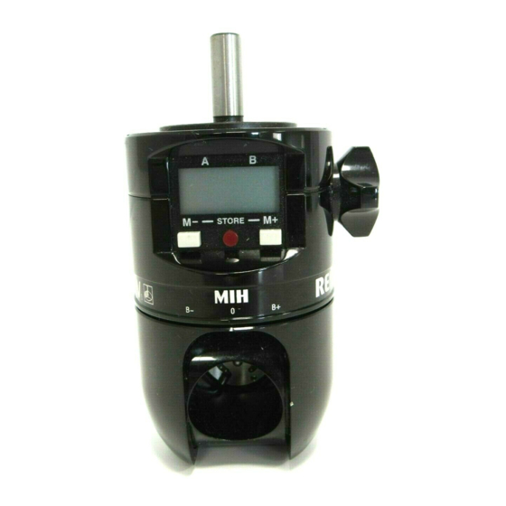
LCD display Probe status LED LCD memory programming buttons Probe autojoint lock/unlock access window Renishaw autojoint probe mounting (recessed into A axis swivel) A axis zero position markers B axis zero position markers MIH - back Refer to fi gure 2 opposite. - Page 13 Major components B axis A axis Figure 1 - MIH (front) Figure 2 - MIH (rear)
-
Page 14: Lcd Display
Major components LCD display Refer to fi gure 3 opposite. A axis positional data (0° to +105°) B axis positional data (-180° to +180°) Low battery indicator Head locked symbol Rotation direction arrows Position confi rmation symbol Sequence store indicator Memory mode indicator Memory number... - Page 15 Major components Figure 3 - LCD display...
-
Page 16: Installation
Installation Installation Fitting the battery Refer to fi gure 4 on page 16. Move MIH to axis positions A0.0, B0.0 and lock up. Unscrew housing retaining screw. Open housing door. Insert battery as shown (negative end fi rst). Close door and secure retaining screw (do not overtighten). -
Page 17: Connection
After changing a probe, unlock and re-lock the head to ensure repeatability. Connection Insert Renishaw 5-pin DIN plug into socket. Pin connections: 1 - Head LED cathode 2 - Ground 3 - Head LED anode... - Page 18 Installation Figure 4 Figure 5 Figure 6...
-
Page 19: Using The Mih
Using the MIH Using the MIH Unlocking the head Both A and B axes are unlocked by a single turn of the thumbwheel in a counter-clockwise direction. The locked (key) symbol on the LCD will disappear. Probes/extensions longer than 150 mm should be supported by hand when locking or unlocking the head. - Page 20 Using the MIH The B axis is positioned by holding the lower housing and rotating until the required position is reached. The A axis is positioned by holding the probe or extension body as close to the head as possible and rotating until the required position is reached.
- Page 21 Using the MIH Figure 8...
-
Page 22: The Lcd/Software Facility
Under normal use, the head will still function for many days after the low battery indicator appears. The MIH also has a user-friendly software facility which is operated by two buttons. The software facility operates in four modes which are entered and exited by button presses and/or time-out periods of non- use. -
Page 23: Memory Mode
Memory mode The user can enter memory mode from simple mode by pressing either the M+ or M- button. In this mode the MIH memory can be programmed or used. In memory mode, chosen head positions can be stored in up to 20 memory stores. Each position is allocated a memory number (0 to 19). -
Page 24: Conserving Battery Life
The LCD/software facility 6.1.5 Conserving battery life Refer to fi gure 9 below. To conserve battery life, the LCD will automatically power down if the head is left in an unlocked state and remains unused for more than 20 seconds. The LCD will return to its exact display before the 20 second time-out upon lock-up. -
Page 25: Datum Mode
The LCD/software facility Datum mode When the battery is fi rst inserted or replaced, the MIH enters a datum mode routine which must be successfully completed prior to use. The A and B axis position detectors within the head require datuming to a zero position before the LCD will display the correct A and B axis positions. - Page 26 The LCD/software facility Step 3 Lock the head in this position and press the M+ and M- buttons simultaneously to reset datum. Step 4 The display will now change to show A and B axis data at A0.0, B0.0. Datum is now set and the A and B axis displays will show positional data when the head is locked and unlocked.
-
Page 27: Simple Mode
The LCD/software facility Simple mode Following insertion of the battery and datuming of the head, the MIH is now ready to be used in simple mode. All data shown in the A and B axis positions on the LCD will be “live”. - Page 28 The LCD/software facility Step 2 Unlock the head and rotate the A and B axes until the required position is reached - in this example. A105.0, B -180.0 If overtravel in either axis occurs, the ‘O-t’ symbol will appear in the axis data on the LCD.
- Page 29 A and B axis positions on the MIH. The MIH can now be used in either of the two pre-qualifi ed positions (A0.0, B0.0 or A105.0, B-180.0) without the need to re-qualify the probe tip after each move. Simply unlock the head, move to the required position and lock up.
-
Page 30: Memory Mode
The LCD/software facility Figure 10 If the head is in a locked position which has previously been stored within the head’s programmable memory function, the memory number corresponding to that position will show on the LCD screen upon lock-up. For further details on the use of the memory function see section 6.4. - Page 31 The LCD/software facility Step 2 The M+ or M- button is pressed to activate memory mode. Memory location 1 is shown on the LCD and the axis data stored in that location is shown in the A and B axis position displays. Because the head is at this position (A0.0, B0.0), the direction arrows do not show, only the position confi...
- Page 32 The LCD/software facility Step 4 Memory location M1 is displayed (A0.0, B0.0) since this was the last memory number used. As the head is not in this position, the direction arrows appear showing the direction in which each axis must be rotated to achieve the position stored in M1 (A0.0, B0.0).
- Page 33 The LCD/software facility The display will then “blink” to show that the position data is stored in the memory. This is confi rmed by A30.0, B30.0 appearing in the A and B axis displays and the direction arrows disappearing, leaving only the confi...
- Page 34 The LCD/software facility Step 8 Unlock the head to display live positional data. The direction arrows remain but stop fl ashing. Step 9 Rotate the A and B axes in the directions indicated by the arrows until both arrows disappear and the position confi rmation block comes on.
-
Page 35: Sequence Mode
The LCD/software facility NOTES: If the head is locked in an incorrect position, the direction arrows will fl ash. The arrows will stop fl ashing after 10 seconds and the display will return to simple mode showing “live” position data. If either button is pressed, the screen will return to the last used memory display. - Page 36 The LCD/software facility Step 1 Pressing the M+ button to edit, the sequence is entered at step 1. The existing contents of this step (in this case memory 1) are also displayed. Step 2 Pressing M+ or M- will increment or decrement the sequence step numbers and the display will show the memory number stored in each sequence step.
- Page 37 The LCD/software facility The S character disappears and the M character will be shown. This confi rms that the sequence step chosen (step 3) is now frozen, and that the new contents can be chosen by pressing either the M+ or M- button to scroll up or down through the memory numbers.
- Page 38 The LCD/software facility Step 5 The sequence now has three steps - step 1 containing memory 1, step 2 containing memory 2 and step 3 containing memory 5. To end the sequence, the end of sequence marker (E) must be placed in sequence step 4.
- Page 39 The LCD/software facility Store E in sequence step 4 by pressing the M+ and M- buttons simultaneously for between half a second and 3 seconds. The sequence is now complete and is as follows - Step 1 (M1), Step 2 (M2), Step 3 (M5), Step 4 (E).
- Page 40 The LCD/software facility Step 7 To exit from editing a sequence, press the M+ and M- buttons simultaneously for longer than 3 seconds. The display will give a choice of either ending sequence mode or using the sequence. Pressing the M- button or taking no action for 5 seconds will return the display to simple mode.
-
Page 41: Using A Sequence
Using a sequence When using a sequence, the only requirement is to position the MIH following the axis direction arrows and lock up once the correct position is reached. On unlock, the sequence will automatically increment to the next step and the direction arrows will indicate the direction each axis must be rotated to, in order to achieve the position stored in that step. - Page 42 The LCD/software facility Step 2 Locking the head in this position returns the display to show the sequence step number and its contents. The corresponding probe tip number can now be selected and points taken. Step 3 When the head is next unlocked, the direction arrows will show the way to achieve the position stored in sequence step 3.
- Page 43 The LCD/software facility Step 4 If the head is accidentally unlocked in a sequence step position before points can be taken, simply re-lock the head and press the M+ or M- buttons to step through the sequence until the correct step is reached. When the last step in the programmed sequence is reached, the sequence will automatically loop back to the fi...
-
Page 44: Summary Of Button Operation
Summary of button operation Summary of button operation Mode Button operation Effect Datum [M+] or [M-] [No change] mode [M+] and [M-] Simple mode entered Simple [M+] or [M-] Memory mode entered mode [M+] and [M-] held for Sequence mode entered longer than 5 seconds Memory [M+]... - Page 45 Summary of button operation Mode Button operation Effect Select [M+] Increments step number sequence [M-] Decrements step number step in [M+] held for longer than Scrolls up step numbers sequence 0.5 seconds edit [M-] held for longer than Scrolls down step 0.5 seconds numbers [M+] and [M-] held for...
- Page 46 Summary of button operation Mode Button operation Effect [M+] Increments step number sequence [M-] Decrements step number mode [M+] held for longer than Scrolls up step numbers 0.5 seconds [M-] held for longer than Scrolls down step 0.5 seconds numbers [M+] and [M-] held for less [No change] than 3 seconds...
-
Page 47: Accessories
The Renishaw manual autojoint probe stand (MAPS) is a low-cost storage rack for up to six autojointed probe/extension combinations. As a complementary product to the MIH, MAPS allows the user to manually insert or remove pre-datumed probe/extension set-ups for protective storage or use with the MIH. MAPS can be either wall- mounted or bolted directly to the CMM table for easy access. -
Page 48: Autojoint Extensions/Adaptors
Renishaw providing easy access to the deepest of features. Utilising the patented Renishaw autojoint, probing set-ups can be simply locked onto the MIH without the need to requalify each time, yielding maximum fl exbility and valuable time saving. PAA3... -
Page 49: Shanks
Refer to fi gure 14 below. Renishaw provide an extensive range of machine mounting shanks to fi t most makes of CMM. Please take care when mounting the MIH with a parallel shank, as any rotational movements will invalidate any stored data. -
Page 50: Dimensions
Dimensions Dimensions Shank mounting face Autojoint location plane 5 mm (0.19 in) Axis of 62 mm rotation (2.44 in) (A axis) 62.5 mm (2.46 in) Figure 16... - Page 51 Mechanical specifi cation Mechanical specifi cation Probe mounting Renishaw autojoint Autojoint repeatability (at 0.5 µm (0.00002 in) * the stylus tip) (2σ) Probe status indicator LED Swept radius 62 mm (5.44 in) * MIH positional repeatability 1 µm (0.00004 in) * (at the stylus tip) (2σ)
-
Page 52: Electrical Specifi Cation
Electrical specifi cation Electrical specifi cation Probe connector Renishaw 5-pin DIN connector Battery type to 6 volt lithium manganese cell (Ø12 mm power LCD [0.48 in] x 25 mm [0.98 in]) Battery type Part number PX28L P-BT03-0004 Alternatives: L544BP K28L V28PXL NOTE: Whilst other battery types (i.e. -
Page 53: Troubleshooting
Troubleshooting Troubleshooting Observation Possible causes Poor repeatability Loose mounting. (probe changing) Dirty or damaged autojoint. Autojoint lock-procedure incorrect. Probe extension too long. Poor repeatability Loose mounting. (head positioning) Head lock-up procedure incorrect with long extensions. Incorrect LCD function Battery power low. No LCD function No battery present or battery inserted incorrectly. - Page 54 Troubleshooting NOTE: The MIH contains no user serviceable parts and should be returned to Renishaw if suspected faulty. Checks/remidial action: • Ensure shank mounting screws are tight and shank is securely mounted in machine machine quill • Inspect autojoint probe connection contacts for damage and contamination.
- Page 55 Check continuity of cabling from head to interface/machine control (refer to installation section for pin connections). • Check probe/extensions are working correctly by exchange/ elimination/continuity check - if faulty return to Renishaw service centre for repair. • Ensure correct connection of interface/machine control.
-
Page 56: Mih Self Test
This test cycles round the LCD displaying each segment in turn. Pressing the M+ button will display all LCD segments simultaneously. Pressing the M- button will display the MIH software version number. Press the M+ and M- buttons simultaneously to transfer to the encoder test. - Page 57 MIH self test 13.2 Encoder test Refer to fi gure 18 below. The head should be locked during this test. Any positional error within the A or B axis encoders will be detected and displayed in the self test. Press M+ and M- simultaneously to transfer to the battery test.
-
Page 58: Battery Test
MIH self test 13.3 Battery test Refer to fi gure 19 below. This function is used by Renishaw when setting the low battery indicator threshold. To step through this function, press the M+ and M- buttons simultaneously to transfer to datum mode. -
Page 59: Maintenance
Maintenance Maintenance The MIH contains no user serviceable parts. The MIH may be cleaned by wiping with a dry, lint-free cloth. - Page 61 Renishaw plc +44 (0)1453 524524 +44 (0)1453 524901 New Mills, Wotton-under-Edge, uk@renishaw.com Gloucestershire, GL12 8JR United Kingdom www.renishaw.com For worldwide contact details, please visit our main website at www.renishaw.com/contact *H-1000-5200-08-A*...
Need help?
Do you have a question about the MIH and is the answer not in the manual?
Questions and answers