
Subscribe to Our Youtube Channel
Related Manuals for Renishaw MH20


Summary of Contents for Renishaw MH20
- Page 1 MH20 and MH20i user's guide www.renishaw.com MH20 and MH20i user's guide Documentation part number: H-1000-5195-06-C Issued 07 2019...
-
Page 2: General Information
Renishaw distributor. Warranty Renishaw plc warrants its equipment for a limited period (as set out in our Standard Terms and Conditions of Sale) provided that it is installed exactly as defined in associated Renishaw documentation. Prior consent must be obtained from Renishaw if non-Renishaw equipment (e.g. interfaces and/or cabling) is to be used or substituted. Failure to comply with this will invalidate the Renishaw warranty. - Page 3 Renishaw probes and associated systems are precision tools used for obtaining precise measurements and must therefore be treated with care. Changes to Renishaw products Renishaw reserves the right to improve, change or modify its hardware or software without incurring any obligations to make changes to Renishaw equipment previously sold. Packaging...
-
Page 4: Product Compliance
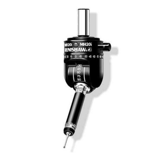
MH20 and MH20i user's guide www.renishaw.com Product compliance EU declaration of conformity Contact Renishaw plc or visit www.renishaw.com/EU for the full EU declaration. REACH regulation Information required by Article 33﴾1﴿ of Regulation ﴾EC﴿ No. 1907/2006 ﴾“REACH”﴿ relating to products containing substances of very high concern (SVHCs) is available at: www.renishaw.com/REACH... - Page 5 Introduction The MH20 and MH20i are manually operated probe heads that articulate to provide orientation of the probing axis. MH20 provides non- repeatable orientation, while MH20i permits repeatable indexing at 15° increments marked on the A and B axes. Both heads feature TP20 kinematic (magnetic) probe mounting, allowing stylus module changes without the need for re-qualification.
-
Page 6: Product Description
MH20 and MH20i The red LED on the front of the head indicates probe status, and can be controlled by either the CMM or a Renishaw probe interface. Conventionally LED ON indicates probe seated (armed), and LED OFF indicates probe triggered. - Page 7 MH20 and MH20i user's guide www.renishaw.com MH20 specification Measuring performance 'TP20 probe module' for TP20 performance details. Technical data Range of articulation A‐axis 93° B‐axis 300° Dual axis lock Single rotary thumbwheel Mounting MS/T range of shanks Cable connection 5-pin DIN socket...
- Page 8 MH20 and MH20i user's guide www.renishaw.com All dimensions are nominal * See 'TP20 specifications'. Issued 07 2019...
- Page 9 MH20 and MH20i user's guide www.renishaw.com Pin no. Function LED cathode Ground LED anode Probe circuit Probe circuit Issued 07 2019...
- Page 10 MH20 and MH20i user's guide www.renishaw.com MH20i specification Measuring performance Positional repeatability ﴾2σ﴿ At stylus tip with TP20 standard force module and 10 mm (0.39 in) 1.5 µm ﴾0.00006 in﴿ stylus length At stylus tip with EM2 94.5 mm (3.72 in) extended module and stylus 2.5 µm ﴾0.0001 in﴿...
- Page 11 MH20 and MH20i user's guide www.renishaw.com All dimensions are nominal * See 'TP20 specifications' † From shank mounting face Issued 07 2019...
- Page 12 MH20 and MH20i user's guide www.renishaw.com Pin no. Function LED cathode Ground LED anode Probe circuit Probe circuit Issued 07 2019...
- Page 13 MH20 and MH20i user's guide www.renishaw.com MH20 and MH20i installation Mounting the shank to the probe head The MH20 and MH20i shanks are factory fitted and are selected by part no. when ordering (see 'Parts list') MH20 shanks cannot be removed...
- Page 14 MH20 and MH20i user's guide www.renishaw.com MH20 operation NOTE: Ensure thumbwheel is unlocked one full turn before re-orientation. Failure to do this will result in excessive wear to the swivel anodised surfaces. Any wear to the swivel is cosmetic only and does not affect performance.
- Page 15 MH20 and MH20i user's guide www.renishaw.com MH20i operation NOTE: Ensure locking lever is in fully locked position before taking gauging points. To change the orientation of the probe: Unlock the head by turning the lock lever to the fully anti-clockwise position Grip the body of the probe (avoid touching the stylus or stylus module) and rotate the B-axis until the desired angle indication on the scale is adjacent to the B‐axis reference mark, increments are in 15°...
- Page 16 * Specified with standard force TP20 module with PS12R stylus and Renishaw PI 4-2 interface ** This can be achieved by taking care when changing modules (see 'Fitting the probe module with stylus on the MH20 or MH20i') *** See 'Probing forces and overtravel limits' for LF, SF, MF and EF trigger force values...
- Page 17 Electrical contact pins automatically complete the probe circuit. Trigger force and length option Seven versions of the TP20 probe module can be used with the MH20 and MH20i, they can be identified by the end cap colour. Standard force (SF) probe module...
- Page 18 MH20 and MH20i user's guide www.renishaw.com Module Stylus length - minimum Stylus length - maximum Overall reach Low force 10 mm 30 mm 94 mm (LF) (0.39 in) (1.18 in) (3.70 in) Standard force 10 mm 50 mm 114 mm (SF) (0.39 in)
- Page 19 1. Select the probe module with the correct trigger force rating for the application (see 'TP20 module selector' and 'TP20 specifications'). 2. Fit the stylus to the probe module, first hand tightening then using the S7 stylus tool (supplied) for final tightness. Renishaw GF styli require an S20 spanner.
- Page 20 MH20 and MH20i user's guide www.renishaw.com TP20 specifications Probing forces and overtravel limits Trigger force - nominal at stylus tip: Probe module TP20-6 way stylus length 10 mm 10 mm 25 mm 50 mm 10 mm 10 mm 10 mm 0.055 N...
- Page 21 MH20 and MH20i user's guide www.renishaw.com Overtravel displacement: Probe module TP20-6 way stylus length 10 mm 10 mm 25 mm 50 mm 10 mm 10 mm 10 mm XY * ±14° ±14° ±14° ±14° ±14° ±14° ±14° (+)Z 3.1 mm 4 mm 3.7 mm...
-
Page 22: Fault Finding
Incorrect unlock procedure. Ensure lock lever is fully rotated to unlock position. Incorrect indexing procedure. Index each axis separately. NOTE: The MH20 and MH20i are not user serviceable and should be returned to Renishaw if suspected faulty. Issued 07 2019... - Page 23 Mounting not secure. Check that the MH20i is correctly mounted on the shank and that the screws are secure. Check clamping mechanism in CMM quill is secure for MH20 and MH20i. MH20 / MH20i not fully locked. Ensure that the thumbwheel / lock lever is turned fully clockwise.
-
Page 24: Maintenance
Maintenance of the TP20 probe is restricted to the periodic cleaning of the kinematic couplings on the probe head and the probe module. To aid cleaning of these couplings, the MH20 and MH20i are supplied with a Renishaw CK200 cleaning kit. Do not use any other cleaning method. -
Page 25: Parts List
TP20 probe modules The MH20 and MH20i can be ordered with either LOW, STD, MED, or EXT force modules (see 'Head and shank combinations - MH20' and 'Head and shank combinations - MH20i' for details). If additional modules are required please refer to the table below for part numbers:... - Page 26 * For MED force module insert 02 * For EXT force module insert 03 e.g. For MH20 with STD force module and MS9/T shank the part number is: A-4043-0109. NOTE: For more information on the Renishaw shank range please refer to H-1000-5050.
- Page 27 * For MED force module insert 02 * For EXT force module insert 03 e.g. For MH20i with MED force module and MS7 shank the part number is: A-4099-0207. NOTE: For more information on the Renishaw shank range please refer to H-1000-5050. Issued 07 2019...
- Page 28 Renishaw plc +44 (0)1453 524524 New Mills, Wotton-under-Edge, +44 (0)1453 524901 Gloucestershire, GL12 8JR United Kingdom www.renishaw.com/cmmsupport For worldwide contact details, please visit our main website at www.renishaw.com/contact Issued 07 2019...
Need help?
Do you have a question about the MH20 and is the answer not in the manual?
Questions and answers