Table of Contents
Advertisement
Quick Links
Advertisement
Table of Contents

Related Manuals for Omron F3SP-U2P


Summary of Contents for Omron F3SP-U2P
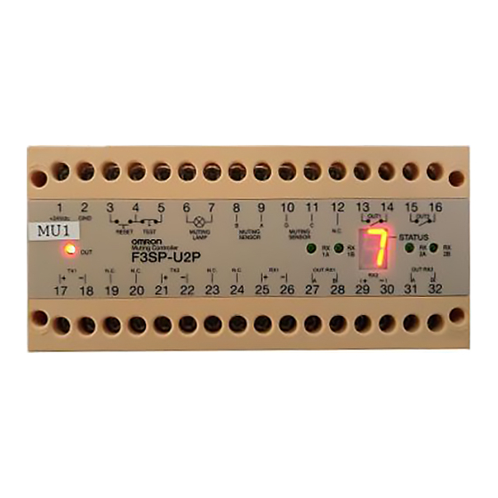
- Page 1 F3SP-U2P Muting Controller Instruction Manual Cat No. Z175-E1-01...
- Page 2 Introduction Thank you for purchasing the F3SP-U2P Muting Controller, (hereinafter referred to as "the F3SP"). This is the Instruction Manual describing the use of the F3SP. Always heed the following points when using the F3SP: • Read this manual and the light curtain’s manual thoroughly and be sure you understand the information provided before attempting to operate the F3SP and light curtain.
- Page 3 Notice Give sufficient safety considerations and make enough allowance with regard to ratings and functions of the system when using the F3SP under following conditions: (1) Conditions or environment not specified in this manual (2) Applications to devices and facilities requiring special safety precautions, such as;...
- Page 4 WARNING Muting sensors must be positioned so that they cannot be activated inadvertently by personnel. The muting lamp for indication “active muting” or “active override” must be positioned in a place where it can be seen from any operative point. Be sure to use the incandescent lamp for the muting lamp and the replacement light bulb.
- Page 5 Notice For your safety, always heed the followings (1) The procedures of installation and inspection in this manual should be read carefully. (2) Loads must satisfy all the conditions below: • Is not short-circuited. • Is not used with current higher than the rating. (3) Be sure to dispose of the F3SP as industrial waste.
-
Page 6: Table Of Contents
Contents Section 1 Description ..................... 1 1-1 Features ......................1 1-2 Functions....................... 2 1-2-1 Interlock function ..................2 1-2-2 Test function ................... 2 1-2-3 Muting function ..................3 1-2-4 Override function ................... 3 1-3 Ratings and Performance ................4 1-4 Indicators and switches................. 6 Section 2 Wiring and Mounting................ -
Page 8: Section 1 Description
Section 1 Description Section 1 Description 1-1 Features The F3SP has two independent microprocessors forming a “dual system” and can be used up to system with safety category 4. One or two light curtains can be input to the F3SP, and input state will be displayed with four input indicators (Green LEDs). -
Page 9: Functions
Section 1 Description 1-2 Functions 1-2-1 Interlock function The auto reset mode and the manual reset mode are selectable features of the F3SP. The selection will be done by dip switch (Please refer to Section 4-1 for selection of dip switch). -
Page 10: Muting Function
Section 1 Description 1-2-3 Muting function The muting function makes it possible to inactivate one or both light curtains in order to allow, for instance, the objects passage without stopping the machine. The F3SP has muting sensor inputs for the activation of this function. The muting sensor A and B controls light curtain 1, as well as muting sensor C and D controls light curtain 2. -
Page 11: Ratings And Performance
Section 1 Description 1-3 Ratings and Performance Type F3SP-U2P Item (NOTE1) Number of light curtains 2 pairs max. Supply voltage (Vs) 24 VDC ±10% (ripple p-p 10% max.) (NOTE1) Power consumption 8W max. (without muting lamp and sensors) Response time 30ms max. - Page 12 Section 1 Description NOTE1: Total power consumption shall not exceed 24W because of internal resettable fuse of F3SP. This includes the consumption of; the light curtains, the muting lamp (3 to 7W), and, the F3SP without load (8W). When total power consumption exceeds 24W by connecting two light curtains, one of them shall be powered directly from DC power supply unit.
-
Page 13: Indicators And Switches
Section 1 Description 1-4 Indicators and switches OUTPUT indicator: Red lit when output OFF, Green lit when output ON. INPUT indicator: Green lit when 24V input. STATUS indicator: Indicates the status of F3SP. DIP SWITCH is used for changing operating mode of the F3SP. For DIP SWITCH configuration, please refer to Section 4-1. -
Page 14: Section 2 Wiring And Mounting
Section 2 Wiring and Mounting Section 2 Wiring and Mounting 2-1 Installation conditions WARNING The F3SP has been designed to be used with the dedicated safety light curtain. It must not be connected to other safety light curtains. The F3SP complies with the requirements for type 4 safety equipment in accordance with the international standards, IEC 61496-1. -
Page 15: Mounting
Section 2 Wiring and Mounting 2-2 Mounting Mount the F3SP on DIN rail with 35mm width. ■When Mounting; ■When Unmounting; Hang the one end of DIN rail to Pull out the hook located at the the F3SP, and push the F3SP bottom of F3SP, using screw until it is locked. -
Page 16: Power Supply
24VDC) Recommended power supply: S82K (15 W, 30 W, 50 W, 90 W type) made by OMRON. (2) The power supply includes a Class 2 circuit supplied by an isolating source that complies with the requirement in the Standard for Class 2 Power Units, UL 1310, or... -
Page 17: Terminal Block Assignment
Section 2 Wiring and Mounting 2-3-2 Terminal block assignment TERMINAL OUTER CONNECTION 1 - 2 Connect to the 24 VDC power supply, note the polarity indicated on the label. 3 - 4 RESET button; connect a normally opened contact (N.O.). 4 - 5 TEST button;... -
Page 18: Wiring Examples
Section 2 Wiring and Mounting 2-3-3 Wiring examples Connection of one safety light curtain Type F3SN-A, Type F3SN-B, or one multi-beam safety sensor Type F3SH-A to the F3SP with two muting sensors. F3SN-A, F3SN-B, or F3SH-A function mode; • Auto-reset mode •... - Page 19 Section 2 Wiring and Mounting Connection of one safety light curtain Type F3SL to the F3SP with two muting sensors. F3SL function mode • Auto-start mode • MPCE monitoring deactivated...
- Page 20 Section 2 Wiring and Mounting Connection of one single beam safety sensor Type F3SS to the F3SP with two muting sensors. F3SS function mode • Auto-start mode...
- Page 21 Section 2 Wiring and Mounting Connection of two safety light curtains F3SN-A, F3SN-B, or two multi- beam safety sensors F3SH-A to the F3SP with four muting sensors. F3SN-A, F3SN-B, or F3SH-A function mode • Auto-reset mode • Auxiliary output set to “Dark on output” [Note]: Mutual interference between 2 light curtains shall be prevented.
-
Page 22: Section 3 Alignment
Section 3 Alignment Section 3 Alignment After having carried out the correct mechanical assembly and the correct connections as described in the previous paragraphs, it is necessary to align the light curtains. Follow the operating guide as follows: Turn off the power supplying the F3SP. Open the TEST contact. -
Page 23: Section 4 Operation
Section 4 Operation Section 4 Operation 4-1 Dip-switches configuration WARNING Configuration of dip switch is must only carries out by qualified person. The configuration shown in the table below must be selected on both sets of dip- switches on the internal board. The description corresponding to the pre-chosen selection is shown below. -
Page 24: Muting Function
Section 4 Operation 4-2 Muting function WARNING Muting and Override function can disable the safety functions of a machine. The proper installation, checkout and operation of a machine and muting system in accordance with all applicable laws and standards, is critical to the safe operation of the machine. -
Page 25: Muting Operations
Section 4 Operation All the light curtains and the muting sensors must be arranged in such a way that the previous material has already passed the last muting sensor before the new material has reached the first muting sensors. Moreover, all the light curtains and the muting sensors must be arranged in such a way that a person cannot enter the dangerous zone inadvertently during the muting condition. - Page 26 Section 4 Operation Application with four muting sensors: Application with two muting sensors: In the above application with two muting sensors, the crossing point of beems from two muting sensors (A and B) is set behind the protective area of the light curtain. This arrangement prevents the light curtain from being muted by a person passing through the crossing point.
- Page 27 Section 4 Operation Application with eight muting sensors for output and input control...
-
Page 28: Override Function
Section 4 Operation 4-3 Override function WARNING Muting and Override function can disable the safety functions of a machine. The proper installation, checkout and operation of a machine and muting system in accordance with all applicable laws and standards, is critical to the safe operation of the machine. -
Page 29: Section 5 Final Checks
Section 5 Final Checks Section 5 Final Checks WARNING Do not use the F3SP until the following inspections are completed. Failure to do so may result in loss of life or serious injury. A qualified person, as determined by local regulations, must confirm that installation and inspection are implemented correctly. -
Page 30: Section 6 Daily Inspection
Section 6 Daily inspection Section 6 Daily inspection WARNING A qualified person, as determined by local regulations, must confirm that installation and inspection are implemented correctly. Be sure to conduct inspection checks as below regularly. Check that there is no person in the hazardous area before operator turns ON the power. -
Page 31: Section 7 Status Indication Codes
Error of muting lamp Check that the muting lamp is not blown incorrectly connected, otherwise contact OMRON. Irreversible system error This type of failure means that the unit or error on the output cannot be used and it is necessary to contacts. -
Page 32: Section 8 Dimensions
Section 8 Dimensions Section 8 Dimensions FRONT VIEW SIDE VIEW 120 mm 150 mm TOP VIEW 75 mm... - Page 33 Rm 1028, Office Building, Beijing Capital Times Square, No.88 West Chang'an Ave., Beijing 100031 CHINA Tel: (86)10-8391-3005 / Fax: (86)10-8391-3688 © OMRON Corporation 2002 All Right Reserved. Note: Specifications subject to change without notice.
Need help?
Do you have a question about the F3SP-U2P and is the answer not in the manual?
Questions and answers