Table of Contents
Advertisement
Quick Links
Technical Procedure
Required Tools:
•
2.5mm Allen Key
•
3mm Allen Key
•
4mm Allen Key
•
5mm Allen Key
•
6mm Allen Key
•
10mm Wrench
•
10mm Socket
•
Ratchet
•
Needle Nose Pliers
1.
Remove the three (3) socket head cap screws se-
curing the brake covers to the unit using a 4mm
allen key
2.
Loosen the screw securing the brake cable to
the brake, then use a 10mm wrench to remove
the M6 nut securing the brake cable to the cable
bracket.
3.
Pull the entire cable from the back of the brake
cable bracket.
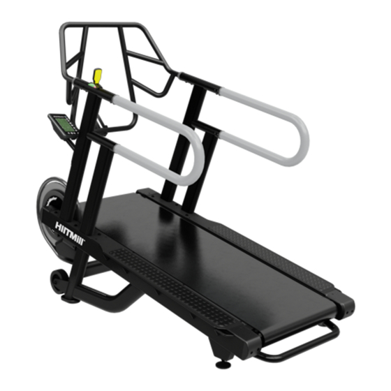
HIITMill (X) Push/Pull Brake Cable Install
Applies to: HIITMill and HIITMill X
Latest Rev.
620-8590 Rev. A
Page 1
Advertisement
Table of Contents

Related Manuals for Stairmaster HIITMill


Summary of Contents for Stairmaster HIITMill
- Page 1 Technical Procedure HIITMill (X) Push/Pull Brake Cable Install Applies to: HIITMill and HIITMill X Required Tools: Latest Rev. • 2.5mm Allen Key • 3mm Allen Key • 4mm Allen Key • 5mm Allen Key • 6mm Allen Key • 10mm Wrench •...
- Page 2 Technical Procedure Remove the brake spring with a pair of needle nose pliers and discard. Use a 4mm allen key to remove the two (2) M8 x 20mm screws from the user left side handrail. Use a 2.5mm allen key to remove the M4 x 8mm screw located in front of the M8 screws removed in Step 5.
- Page 3 Technical Procedure Use a 3mm allen key to remove the two (2) M5 x 16mm screws securing resistance lever covers to the user left handrail. Carefully pull up on the resistance lever to re- move both the resistance lever assembly and the brake cable.
- Page 4 Technical Procedure Feed one end of the new push/pull brake cable up through the bottom of the frame where indicated. NOTE: Some early production units may have a circu- lar opening rather than rectanguar as shown right. Pull the push/pull brake cable up through and out of the hole in the frame.
- Page 5 Technical Procedure After the new cable is routed out of the top of the handrail, attach the cable end fitting to the cable, thread the fitting about 3/4 down the cable. thread one of the cable fitting ends onto the top of the cable. Set the bottom 7/16”...
- Page 6 Technical Procedure Ensure that the bottom nut located on the cable is threaded all the way down then secure the bottom end of the new brake cable into the new cable bracket. Use a 5mm allen key and a 10mm wrench to re- move and replace the brake screw with the screw supplied.
- Page 7 Technical Procedure Install the new resistance lever covers using a 3mm allen key. Ensure that the STOP icon is fac- ing the rear of the machine. Test the tension on the new cable by pulling the lever all the way back to the STOP position, the belt should not be moving while standing on the unit while the lever is in this postion.
Need help?
Do you have a question about the HIITMill and is the answer not in the manual?
Questions and answers