Advertisement
Advertisement
Table of Contents

Related Manuals for Stairmaster HIITMil


Summary of Contents for Stairmaster HIITMil
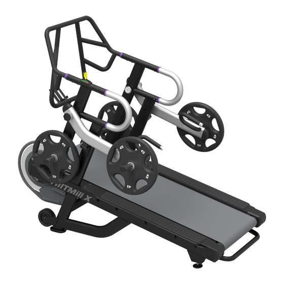
- Page 1 StairMaster ® HIITMill / HIITMill X ™ ™ Install Manual...
-
Page 2: Table Of Contents
TABLE OF CONTENTS INTRODUCTION .................................. 01 Product Specifications ..........................02 ASSEMBLY INSTRUCTIONS ................................03 INSTALL CHECKLIST .................................. 05 CORRECTIVE PROCEDURES .................................. Belt Sticking / Not Moving ..........................06 Brake Misaligned ............................. 07... -
Page 3: Introduction
Introduction We are excited to be shipping the new StairMaster HIITMill and HIITMill X to our customers worldwide and the response from end users has been extremely positive. As with any new product launch we are responding to early production issues at installation that we want to address and correct prior to use. -
Page 4: Product Specifications
Product Specifications MANUFACTURER: HIITMill CORE HEALTH & FITNESS Dimensions: 37” W x 77” L x 65” H 4400 NE 77th Avenue, Suite 300 94 cm x 196 cm x 166 cm Vancouver, WA 98662 Weight: 390 lbs / 177 kg Telephone: (888) 678-2476 http://www.corehealthandfitness.com HIITMill X... -
Page 5: Assembly Instructions
Assembly Instructions STEP 1: NOTE: The user left side handrail is attached to the lower frame via the brake cable. DO NOT pick the unit up until after securing the handrail to the frame. NOTE: Do not tighten any hardware until instructed to do so. With a 5mm allen key, remove the two (2) screws and washers se- curing the flywheel guard to the frame then slide the user left side handrail between the frame and the flywheel guard. - Page 6 STEP 4: Install the main handlebar using a 5mm allen key to secure four (4) pieces each of the M8 x 20mm screws, torque to 24Nm (18 Ft-Lb). Secure left and right side beauty rings using a 2.5mm allen key and one (1) piece each of the M4 x 8mm screws, torque to 4Nm (3Ft-Lb).
-
Page 7: Install Checklist
Install Checklist All hardware is tight and torqued appropriately. Any excess silicone has been removed from underside of HIITMill X belt. Brake checked to ensure flywheel clearance. Protective decal film has been removed. -
Page 8: Belt Sticking/Not Moving
Belt Sticking/Not Moving (HIITMill X Only) 1. Inspect the bottom left and right corners of the deck for excess silicone (Fig. 1). Some silicone residue is nor- mal but it should not be dripping down the deck. 2. Inspect the underside of the belt, run your hand along the underside of the belt to check for excess Fig. -
Page 9: Brake Misaligned
Brake Misaligned (HIITMill + HIITMill X) 1. If during use the brake is rubbing on the flywheel, the brake will need to be inspected and aligned. To do this, first remove the shrouds covering the brake assembly (Fig. 1). Fig. 1 2. - Page 10 637-4494 REV B © 2017 CORE HEALTH & FITNESS, LLC...
Need help?
Do you have a question about the HIITMil and is the answer not in the manual?
Questions and answers