Table of Contents
Advertisement
Quick Links
ECS-PMC/FPGA
®
PMC EtherCAT
Slave Interface
Hardware Manual
to Product E.1104.02
ECS-PMC/FPGA
Hardware Manual • Doc. No.: E.1104.21 / Rev. 1.1
Page 1 of 26
esd electronic system design gmbh
Vahrenwalder Str. 207 • 30165 Hannover • Germany
http://www.esd.eu
Phone: +49 (0) 511 3 72 98-0 • Fax: +49 (0) 511 3 72 98-68
Advertisement
Table of Contents

Subscribe to Our Youtube Channel
Related Manuals for ESD ECS-PMC/FPGA


Summary of Contents for ESD ECS-PMC/FPGA
- Page 1 ECS-PMC/FPGA Hardware Manual • Doc. No.: E.1104.21 / Rev. 1.1 Page 1 of 26 esd electronic system design gmbh Vahrenwalder Str. 207 • 30165 Hannover • Germany http://www.esd.eu Phone: +49 (0) 511 3 72 98-0 • Fax: +49 (0) 511 3 72 98-68...
- Page 2 The information in this document has been carefully checked and is believed to be entirely reliable. esd makes no warranty of any kind with regard to the material in this document, and assumes no responsibility for any errors that may appear in this document. In particular descriptions and technical data specified in this document may not be constituted to be guaranteed product features in any legal sense.
- Page 3 New picture on page 1 Conformity note inserted under Safety Information 2015-07-17 Figure with new front panel inserted Safety information revised Technical details are subject to change without further notice. ECS-PMC/FPGA Hardware Manual • Doc. No.: E.1104.21 / Rev. 1.1 Page 3 of 26...
- Page 4 It is the responsibility of the device's user to take care that necessary safety precautions for the device's network interface are in place.
-
Page 5: Table Of Contents
Connector Assignments......................22 7.1 EtherCAT..........................22 Connectors........................23 7.2.1 PMC Connector Pn1 (P11)..................23 7.2.2 PMC Connector Pn2 (P12)..................24 7.2.3 PMC Connector Pn4 (P14)..................25 Order Information........................26 ECS-PMC/FPGA Hardware Manual • Doc. No.: E.1104.21 / Rev. 1.1 Page 5 of 26... - Page 6 Abbreviations Application Programming Interface Central Processing Unit EtherCAT Slave Controller EtherCAT Slave Information Hardware Input/Output n.a. not applicable n.c. not connected Operating System Software Development Kit Page 6 of 26 Hardware Manual • Doc. No.: E.1104.21 / Rev. 1.1 ECS-PMC/FPGA...
-
Page 7: Quick Start
Quick Start 1. Quick Start This chapter describes first steps with the ECS-PMC/FPGA. It uses an esd EtherCAT Slave Stack sample application and the esd EtherCAT Workbench to show the functionality of the ECS- PMC/FPGA. 1.1 Requirements EtherCAT knowledge. The ETG (EtherCAT Technology Group, http://ethercat.org) has •... -
Page 8: Driver Installation
64 bit Windows) and click Next: Figure 2: Update Driver Software 1.3.2 Linux The Linux driver for the esd EtherCAT slave device (ECS-PMC/FPGA) is usually delivered as source code. Please refer to “.../driver/ECS-.../linux/README” from the extracted Slave Stack Linux archive. -
Page 9: Sample Slave Application
After the Workbench was (re)started a slave scan can be performed. Use the Online button to let the Workbench connect to its included Master and click the Scan button then: Figure 4: Scan result showing “Slave 1 (ECS-PMC/FPGA)”, (picture detail) ECS-PMC/FPGA Hardware Manual •... - Page 10 Figure 5: Process data view with “Slave 1 (ECS-PMC/FPGA)”, (picture detail) Double click the output (“Slave 1 (ECS-PMC/FPGA).RxPDO1.Output1”) to write a new value to the slave. The Slave sample application shows the new value in its console output, for example: “[Application] *** output1 changed to 1234”...
-
Page 11: Further Steps
EtherCAT Technology Group http:\\ethercat.org. This includes using your own EtherCAT vendor ID and testing the final product with the EtherCAT CTT (Conformance Test Tool). ECS-PMC/FPGA Hardware Manual • Doc. No.: E.1104.21 / Rev. 1.1 Page 11 of 26... -
Page 12: Overview
16MByte Sensor 32KBit Serial No. Figure 6: Block circuit diagram of ECS-PMC/FPGA The ECS-PMC/FPGA is an EtherCAT Slave Controller Board in a IEEE 1386.1 (PMC) form factor. It utilizes a Beckhoff ® IP-core which is implemented in an Altera ®... -
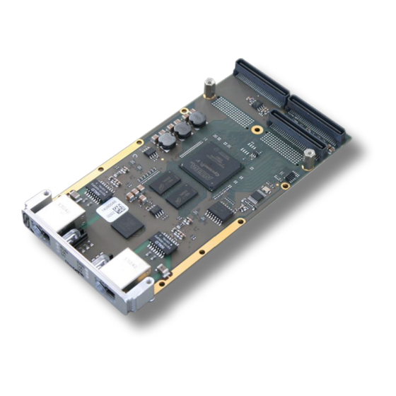
Page 13: Pcb View With Connectors
3. PCB View with Connectors Figure 7: PCB top view See also chapter “Connector Assignments”, from page 22 on, for the signal assignments of the connectors. ECS-PMC/FPGA Hardware Manual • Doc. No.: E.1104.21 / Rev. 1.1 Page 13 of 26... -
Page 14: Leds
LED blinking cycle: 200 ms on, 1000 ms off. double flash LED blinking cycle: 200 ms on, 200 ms off, 200 ms on, 1000 ms off. Table 1: LED states (according to ETG.1300-documentation) Page 14 of 26 Hardware Manual • Doc. No.: E.1104.21 / Rev. 1.1 ECS-PMC/FPGA... - Page 15 LED900B port OUT blinking Ethernet Activity (Receiving Ethernet data packages) User LED2 yellow user defined via FPGA and driver LED900A Table 2: Description of LEDs ECS-PMC/FPGA Hardware Manual • Doc. No.: E.1104.21 / Rev. 1.1 Page 15 of 26...
-
Page 16: Hardware Installation
Pay attention that the PMC module is correctly installed on the carrier board. Fix the ECS-PMC/FPGA with the screws on the carrier board. Use the M 2.5 x 6 mm screws which are contained in the product package of the module. - Page 17 7. Install the carrier board in your system. 8. If necessary close the case again. 9. Connect the EtherCAT interfaces via the connectors in the front panel of the ECS-PMC/FPGA. 10. Connect the system to mains again (mains connector or safety fuse).
-
Page 18: Technical Data
16 Mbyte – for active serial Boot Option Ethernet 2 x Micrel KSZ8081MNX Serial I2C EEPROM 32 KBit I2C Temperature Sensor Texas Instruments TMP100 Table 4: Hardware components Page 18 of 26 Hardware Manual • Doc. No.: E.1104.21 / Rev. 1.1 ECS-PMC/FPGA... -
Page 19: Fpga
IN and OUT Connector 2 x RJ45 socket with separate LEDs for status indication (see “LED Indication” page 14) Table 7: Data of the EtherCAT interface ECS-PMC/FPGA Hardware Manual • Doc. No.: E.1104.21 / Rev. 1.1 Page 19 of 26... -
Page 20: Temperature Sensor
The lines include a 33 Ω series resistors near to the FPGA. Controller Integrated in FPGA Table 10: Data of the Spare I/O on PMC Page 20 of 26 Hardware Manual • Doc. No.: E.1104.21 / Rev. 1.1 ECS-PMC/FPGA... -
Page 21: Software Support
The FPGA contains Bus Master DMA Support to offload the CPU from copying the output process image data into the host memory. This is utilized by the esd EtherCAT Slave Stack. Please refer to the EtherCAT Slave Stack manual (see “Order Information” page 26) for further information. -
Page 22: Connector Assignments
- ... reserved for future applications, do not connect! Shield... case shield, connected with the front panel of the ECS-PMC/FPGA. Note: Permissible cable types: Cables of category 5e or higher have to be used to grant the function in networks with up to 100 Mbits/s. -
Page 23: Pmc Connectors
Connector Assignments 7.2 PMC Connectors The ECS-PMC/FPGA module uses the PMC connectors Pn1, Pn2 and Pn4. Pn1 and Pn2 provide the PCI interface and power supply connection. Pn4 has a complete module specific pin out. 7.2.1 PMC Connector Pn1 (P11) -
Page 24: Pmc Connector Pn2 (P12)
This pin is not connected at the module. Pins with signal names in brackets are reserved for future use. These signals are not ( … ) supported at the moment. Page 24 of 26 Hardware Manual • Doc. No.: E.1104.21 / Rev. 1.1 ECS-PMC/FPGA... -
Page 25: Pmc Connector Pn4 (P14)
This pin is not connected at the module. PMC_IOx PMC IO signals (x = 0 - 15) Latch_x, Sync_x Sync and Latch signals (x = 0,1) Reference potential ECS-PMC/FPGA Hardware Manual • Doc. No.: E.1104.21 / Rev. 1.1 Page 25 of 26... -
Page 26: Order Information
Table 11: Order information PDF Manuals Manuals are available in English and usually in German as well. For availability of English manuals see table below. Please download the manuals as PDF documents from our esd website www.esd.eu for free. Manuals Order No.
Need help?
Do you have a question about the ECS-PMC/FPGA and is the answer not in the manual?
Questions and answers