Table of Contents
Advertisement
Quick Links
ECS-XMC/FPGA
®
XMC EtherCAT
Slave Interface
Hardware Manual
to Product E.1102.02
ECS-XMC/FPGA
Hardware Manual • Doc. No.: E.1102.21 / Rev. 1.3
Page 1 of 27
esd electronics gmbh
Vahrenwalder Str. 207 • 30165 Hannover • Germany
http://www.esd.eu
Phone: +49 (0) 511 3 72 98-0 • Fax: +49 (0) 511 3 72 98-68
Advertisement
Table of Contents

Subscribe to Our Youtube Channel
Related Manuals for ESD ECS-XMC


Summary of Contents for ESD ECS-XMC
- Page 1 ECS-XMC/FPGA Hardware Manual • Doc. No.: E.1102.21 / Rev. 1.3 Page 1 of 27 esd electronics gmbh Vahrenwalder Str. 207 • 30165 Hannover • Germany http://www.esd.eu Phone: +49 (0) 511 3 72 98-0 • Fax: +49 (0) 511 3 72 98-68...
- Page 2 design.
- Page 3 Document file: I:\Texte\Doku\MANUALS\EtherCAT\ECS-XMC-FPGA\Englisch\ECS-XMC-FPGA_Manual_en_13.odt Date of print: 2019-12-02 Document DOC0800 type number: Hardware version: Document History The changes in the document listed below affect changes in the hardware as well as changes in the description of the facts, only. Rev. Chapter...
- Page 4 This NOTICE statement contains the general mandatory sign and gives information that must be heeded and complied with for a safe use. INFORMATION INFORMATION Notes to point out something important or useful. Page 4 of 27 Hardware Manual • Doc. No.: E.1102.21 / Rev. 1.3 ECS-XMC/FPGA...
-
Page 5: Safety Instructions
It is the responsibility of the device's user to take care that necessary safety precautions for the device's network interface are in place. - Page 6 The intended use of the ECS-XMC/FPGA is the operation as XMC EtherCAT® Slave Interface. The guarantee given by esd does not cover damages which result from improper use, usage not in accordance with regulations or disregard of safety instructions and warnings.
-
Page 7: Table Of Contents
Support......................... 22 6.9.1 License........................22 Connector Assignments......................23 7.1 EtherCAT..........................23 XMC - P15........................... 24 XMC - P16........................... 25 Declaration of Conformity......................26 Order Information........................27 ECS-XMC/FPGA Hardware Manual • Doc. No.: E.1102.21 / Rev. 1.3 Page 7 of 27... -
Page 8: Quick Start
Quick Start 1. Quick Start This chapter describes first steps with the ECS-XMC/FPGA. It uses an esd EtherCAT Slave Stack sample application and the esd EtherCAT Workbench to show the functionality of the ECS- XMC/FPGA. 1.1 Requirements EtherCAT knowledge. The ETG (EtherCAT Technology Group, http://ethercat.org) has •... -
Page 9: Driver Installation
64 bit Windows) and click Next: Figure 2: Update Driver Software 1.3.2 Linux The Linux driver for the esd EtherCAT slave device (ECS-XMC/FPGA) is usually delivered as source code. Please refer to “.../driver/ECS-.../linux/README” from the extracted Slave Stack Linux archive. -
Page 10: Sample Slave Application
After the Workbench was (re)started a slave scan can be performed. Use the Online button to let the Workbench connect to its included Master and click the Scan button then: Figure 4: Scan result showing “Slave 1 (ECS-XMC/FPGA)”, (picture detail) Page 10 of 27 Hardware Manual •... - Page 11 Figure 5: Process data view with “Slave 1 (ECS-XMC/FPGA)”, (picture detail) Double click the output (“Slave 1 (ECS-XMC/FPGA).RxPDO1.Output1”) to write a new value to the slave. The Slave sample application shows the new value in its console output, for example: “[Application] *** output1 changed to 1234”...
-
Page 12: Further Steps
EtherCAT Technology Group http:\\ethercat.org. This includes using your own EtherCAT vendor ID and testing the final product with the EtherCAT CTT (Conformance Test Tool). Page 12 of 27 Hardware Manual • Doc. No.: E.1102.21 / Rev. 1.3 ECS-XMC/FPGA... -
Page 13: Overview
The FPGA contains Bus Master DMA support to offload the CPU from copying the output process image data into the host memory. This is utilized by the esd EtherCAT Slave Stack. Because of this simple hardware topology and the use of a “soft” controller the design offers a maximum of flexibility. -
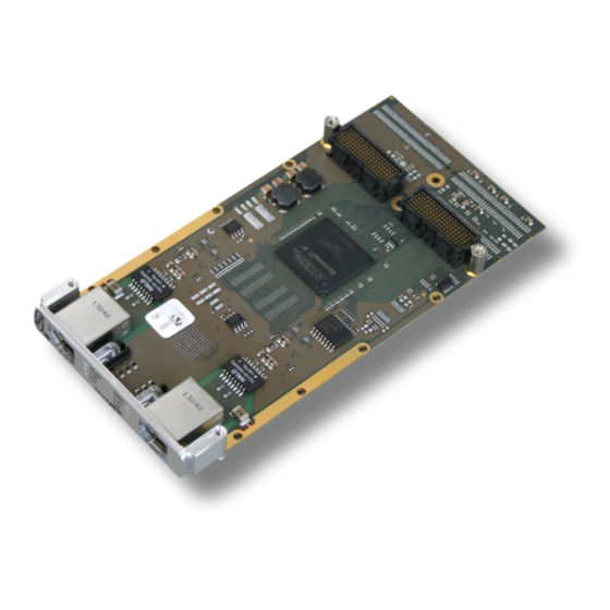
Page 14: Pcb View With Connectors
3. PCB View with Connectors Figure 7: PCB top view See also chapter “Connector Assignments”, from page 23 on, for the signal assignments of the connectors. Page 14 of 27 Hardware Manual • Doc. No.: E.1102.21 / Rev. 1.3 ECS-XMC/FPGA... -
Page 15: Leds
LED blinking cycle: 200 ms on, 1000 ms off. double flash LED blinking cycle: 200 ms on, 200 ms off, 200 ms on, 1000 ms off. Table 1: LED states (according to ETG.1300-documentation) ECS-XMC/FPGA Hardware Manual • Doc. No.: E.1102.21 / Rev. 1.3 Page 15 of 27... - Page 16 LED900B port OUT blinking Ethernet Activity (Receiving Ethernet data packages) User LED2 yellow user defined via FPGA and driver LED900A Table 2: Description of LEDs Page 16 of 27 Hardware Manual • Doc. No.: E.1102.21 / Rev. 1.3 ECS-XMC/FPGA...
-
Page 17: Hardware Installation
Pay attention that the XMC module is correctly installed on the carrier board. Fix the ECS-XMC/FPGA with the screws on the carrier board. Use the M 2.5 x 6 mm screws which are contained in the product package of the module. - Page 18 13. For the installation of the software drivers read the chapter “Quick Start“, from page 8 and go on with the procedure described in the section “Steps“. Page 18 of 27 Hardware Manual • Doc. No.: E.1102.21 / Rev. 1.3 ECS-XMC/FPGA...
-
Page 19: Technical Data
16 Mbyte – for active serial Boot Option Ethernet 2 x Micrel KSZ8081MNX Serial I2C EEPROM 32KBit I2C Temperature Sensor Texas Instruments TMP100 Table 4: Hardware components ECS-XMC/FPGA Hardware Manual • Doc. No.: E.1102.21 / Rev. 1.3 Page 19 of 27... -
Page 20: Fpga
IN and OUT Connector 2 x RJ45 socket with separate LEDs for status indication (see “LED Indication” page 15) Table 7: Data of the EtherCAT interface Page 20 of 27 Hardware Manual • Doc. No.: E.1102.21 / Rev. 1.3 ECS-XMC/FPGA... -
Page 21: Temperature Sensor
The lines include a 33 Ω series resistors near to the FPGA. Controller Integrated in FPGA Table 10: Data of the Spare I/O on XMC ECS-XMC/FPGA Hardware Manual • Doc. No.: E.1102.21 / Rev. 1.3 Page 21 of 27... -
Page 22: Software Support
The FPGA contains Bus Master DMA Support to offload the CPU from copying the output process image data into the host memory. This is utilized by the esd EtherCAT Slave Stack. Please refer to the EtherCAT Slave Stack manual (see “Order Information” page 27) for further information. -
Page 23: Connector Assignments
Permissible cable types: Cables of category CAT5 or higher have to be used to grant the function in networks with up to 100 Mbits/s. esd grants the EC conformity of the product if the wiring is carried out with shielded twisted pair cables. -
Page 24: Xmc - P15
PCIe_Rx_L3n n.c. EEPROM_GA2 EEPROM_SDA n.c. n.c. n.c. n.c. n.c. n.c. EEPROM_WE EEPROM_SCL n.c. n.c. n.c. n.c. n.c. n.c. n.c. n.c. REFCLK_0p REFCLK_0n n.c. WAKE# n.c. n.c. Page 24 of 27 Hardware Manual • Doc. No.: E.1102.21 / Rev. 1.3 ECS-XMC/FPGA... -
Page 25: Xmc - P16
FPGA Pin (x = letter K, L, M, N, P, R or T; yy = number 16 to 22; for example xyy: P17) reference potential n.c. not connected ECS-XMC/FPGA Hardware Manual • Doc. No.: E.1102.21 / Rev. 1.3 Page 25 of 27... -
Page 26: Declaration Of Conformity
Declaration of Conformity 8. Declaration of Conformity Page 26 of 27 Hardware Manual • Doc. No.: E.1102.21 / Rev. 1.3 ECS-XMC/FPGA... -
Page 27: Order Information
Table 11: Order information PDF Manuals Manuals are available in English and usually in German as well. For availability of English manuals see table below. Please download the manuals as PDF documents from our esd website www.esd.eu for free. Manuals Order No.
Need help?
Do you have a question about the ECS-XMC and is the answer not in the manual?
Questions and answers