Table of Contents
Advertisement
Quick Links
https://appliancetechmanuals.com
A product of Vulcan-Hart
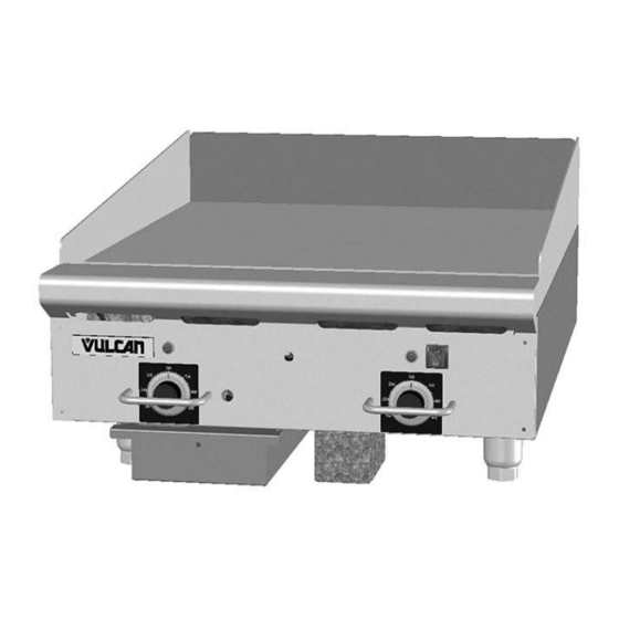
24RRG Shown
This Manual is prepared for the use of trained Vulcan Service
Technicians and should not be used by those not properly
qualified.
This manual is not intended to be all encompassing. If you have
not attended a Vulcan Service School for this product, you should
read, in its entirety, the repair procedure you wish to perform to
determine if you have the necessary tools, instruments and skills
required to perform the procedure. Procedures for which you do
not have the necessary tools, instruments and skills should be
performed by a trained Vulcan Service Technician.
The reproduction, transfer, sale or other use of this Manual,
without the express written consent of Vulcan, is prohibited.
This manual has been provided to you by ITW Food Equipment
Group LLC ("ITW FEG") without charge and remains the property
of ITW FEG, and by accepting this manual you agree that you will
return it to ITW FEG promptly upon its request for such return at
any time in the future.
SERVICE MANUAL
RRG SERIES HEAVY DUTY GAS
GRIDDLE
24RRG
36RRG
48RRG
60RRG
- NOTICE -
3600 North Point Blvd Baltimore, MD 21222
ML-135339-00024
ML-135340-00036
ML-135341-00048
ML-135342-00060
F45514 (0214)
Advertisement
Table of Contents

Related Manuals for Vulcan-Hart RRG Series


Summary of Contents for Vulcan-Hart RRG Series
- Page 1 SERVICE MANUAL RRG SERIES HEAVY DUTY GAS GRIDDLE 24RRG ML-135339-00024 36RRG ML-135340-00036 48RRG ML-135341-00048 60RRG ML-135342-00060 24RRG Shown - NOTICE - This Manual is prepared for the use of trained Vulcan Service Technicians and should not be used by those not properly qualified.
-
Page 2: Table Of Contents
RRG SERIES HEAVY DUTY GAS GRIDDLE TABLE OF CONTENTS GENERAL ....................3 INTRODUCTION . -
Page 3: General
RRG SERIES HEAVY DUTY GAS GRIDDLE - GENERAL GENERAL INTRODUCTION SPECIFICATIONS This Service Manual covers specific service Electrical information related to the models listed on the front - 120VAC 50/60Hz 1 Amp single phase. cover. Procedures in this manual will apply to all RRG Heavy Duty Gas Griddles unless otherwise specified. - Page 4 RRG SERIES HEAVY DUTY GAS GRIDDLE - GENERAL • Thread sealant suitable for use with natural or propane gas. Special • Torque wrench capable of measuring at least 25 in-lbs. for tightening thermocouple probe to griddle plate. Bolt size 5/16"-18.
-
Page 5: Removal And Replacement Of Parts
RRG SERIES HEAVY DUTY GAS GRIDDLE - REMOVAL AND REPLACEMENT OF PARTS REMOVAL AND REPLACEMENT OF PARTS Remove all screws from rear of griddle securing CONTROL PANEL the back panel. Disconnect the electrical power to the machine and follow lockout / tagout procedures. -
Page 6: Thermocouple
RRG SERIES HEAVY DUTY GAS GRIDDLE - REMOVAL AND REPLACEMENT OF PARTS THERMOCOUPLE Disconnect the electrical power to the machine and follow lockout / tagout procedures. Shut off the gas before servicing the unit. All gas joints disturbed during servicing must be checked for leaks. -
Page 7: Burner
RRG SERIES HEAVY DUTY GAS GRIDDLE - REMOVAL AND REPLACEMENT OF PARTS BURNER Disconnect the electrical power to the machine and follow lockout / tagout procedures. Shut off the gas before servicing the unit. All gas joints disturbed during servicing must be checked for leaks. -
Page 8: Ignition Module
RRG SERIES HEAVY DUTY GAS GRIDDLE - REMOVAL AND REPLACEMENT OF PARTS Access ignition module, and disconnect high voltage spark wire. Fig. 9 Remove CONTROL PANEL. Lift griddle at the front and support it from Fig. 11 underneath for access to the pilot. (Be aware of... -
Page 9: Dual Solenoid Valves
RRG SERIES HEAVY DUTY GAS GRIDDLE - REMOVAL AND REPLACEMENT OF PARTS DUAL SOLENOID VALVES Disconnect the electrical power to the machine and follow lockout / tagout procedures. Shut off the gas before servicing the unit. All gas joints disturbed during servicing must be checked for leaks. -
Page 10: Single Solenoid Valve
RRG SERIES HEAVY DUTY GAS GRIDDLE - REMOVAL AND REPLACEMENT OF PARTS Disconnect compression fitting and remove flex tubing from front of single solenoid valve. Fig. 15 Remove the three NPT elbows. Two on front and one on the back of dual solenoid valve. -
Page 11: Gas Pressure Regulator
RRG SERIES HEAVY DUTY GAS GRIDDLE - REMOVAL AND REPLACEMENT OF PARTS Adjust regulator as outlined in REGULATOR GAS PRESSURE REGULATOR ADJUSTMENT. GRIDDLE PLATE ASSEMBLY Disconnect the electrical power to the machine and follow lockout / tagout procedures. Disconnect the electrical power to the machine and follow lockout / tagout procedures. -
Page 12: Service Procedures And Adjustments
RRG SERIES HEAVY DUTY GAS GRIDDLE - SERVICE PROCEDURES AND ADJUSTMENTS SERVICE PROCEDURES AND ADJUSTMENTS • If temperature measurement is outside of TEMPERATURE CONTROL tolerance then temperature control must be CALIBRATION calibrated. CALIBRATING TEMPERATURE CONTROL NOTE: Ensure the griddle is level before performing... -
Page 13: Burner Air Shutter Adjustment
RRG SERIES HEAVY DUTY GAS GRIDDLE - SERVICE PROCEDURES AND ADJUSTMENTS Install burner. BURNER AIR SHUTTER Install GAS PRESSURE REGULATOR. ADJUSTMENT Connect power to machine. Turn on power and rotate temperature controller Disconnect the to call for heat. electrical power to the machine and Observe flame from back of machine. -
Page 14: Burner Nozzle Check
RRG SERIES HEAVY DUTY GAS GRIDDLE - SERVICE PROCEDURES AND ADJUSTMENTS Fig. 24 Insert a flat edge screwdriver through the top of the regulator. While watching the manometer, turn the adjusting screw clockwise to increase Fig. 22 pressure and counterclockwise to decrease Remove pressure tap plug and connect pressure. -
Page 15: Thermocouple Test
RRG SERIES HEAVY DUTY GAS GRIDDLE - SERVICE PROCEDURES AND ADJUSTMENTS TEMPERATURE CONTROLLER TEST Disconnect the electrical power to the machine and follow lockout / tagout procedures. Access the TEMPERATURE CONTROLLER. Connect power to the machine. Turn on the power switch. -
Page 16: Ignition Module Test
RRG SERIES HEAVY DUTY GAS GRIDDLE - SERVICE PROCEDURES AND ADJUSTMENTS IGNITION MODULE TEST PILOT BURNER FLAME ADJUSTMENT NOTE: Sparking will continue until pilot flame is established, at which point sparking will terminate. If no pilot flame is established the sparking will continue Disconnect the until power is removed from unit. -
Page 17: Solenoid Valve Tests
RRG SERIES HEAVY DUTY GAS GRIDDLE - SERVICE PROCEDURES AND ADJUSTMENTS Fig. 30 To increase pilot flame turn valve needle counterclockwise. To decrease pilot flame, turn valve needle clockwise. Once pilot flame is adjusted correctly, turn off Fig. 31 power switch. -
Page 18: Electrical Operation
RRG SERIES HEAVY DUTY GAS GRIDDLE - ELECTRICAL OPERATION ELECTRICAL OPERATION COMPONENT FUNCTION Temperature Control . . . Controls griddle surface temperature for the individual heat zone by monitoring thermocouple input (K type ). Temperature Probe . . . - Page 19 RRG SERIES HEAVY DUTY GAS GRIDDLE - ELECTRICAL OPERATION each of the installed temperature controllers and Indicator lights are dimly lit. ignition modules on the griddle. Turn temperature dials to 350°F. Single solenoid valve energized and gas Temperature controller N.O. contacts close flows to pilot burner.
-
Page 20: 24" Griddle - Wiring Diagram
RRG SERIES HEAVY DUTY GAS GRIDDLE - ELECTRICAL OPERATION 24" GRIDDLE - WIRING DIAGRAM 24" GRIDDLE - WIRING DIAGRAM F45514 (0214) Page 20 of 24... -
Page 21: 36" Griddle - Wiring Diagram
RRG SERIES HEAVY DUTY GAS GRIDDLE - ELECTRICAL OPERATION 36" GRIDDLE - WIRING DIAGRAM 36" GRIDDLE - WIRING DIAGRAM Page 21 of 24 F45514 (0214) -
Page 22: 48" Griddle - Wiring Diagram
RRG SERIES HEAVY DUTY GAS GRIDDLE - ELECTRICAL OPERATION 48" GRIDDLE - WIRING DIAGRAM 48" GRIDDLE - WIRING DIAGRAM F45514 (0214) Page 22 of 24... -
Page 23: 60" Griddle - Wiring Diagram
RRG SERIES HEAVY DUTY GAS GRIDDLE - ELECTRICAL OPERATION 60" GRIDDLE - WIRING DIAGRAM 60" GRIDDLE - WIRING DIAGRAM Page 23 of 24 F45514 (0214) -
Page 24: Troubleshooting
RRG SERIES HEAVY DUTY GAS GRIDDLE - TROUBLESHOOTING TROUBLESHOOTING TROUBLESHOOTING PROBLEM POSSIBLE CAUSES Power switch inoperative. No power to ignition module. Ignition module not properly grounded No spark to ignite pilot burner. Ignition module malfunction. Spark gap incorrect. Ignitor/flame sense wire inoperative.
Need help?
Do you have a question about the RRG Series and is the answer not in the manual?
Questions and answers