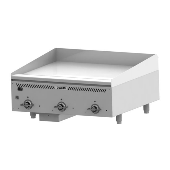
Vulcan-Hart VCCG36 Installation & Operation Manual
Heavy duty gas griddles
Hide thumbs
Also See for VCCG36:
- Service manual (26 pages) ,
- Installation & operation manual (38 pages) ,
- Service manual (26 pages)
Table of Contents
Advertisement
Quick Links
INSTALLATION & OPERATION MANUAL
HEAVY DUTY GAS GRIDDLES
For additional information on Vulcan or to locate an authorized parts and
service provider in your area, visit our website at www.vulcanequipment.com
©ITW Food Equipment Group, LLC
3600 North Point Blvd.
Baltimore, MD 21222
VCCG36
MODELS
VCCG24
VCCG36
VCCG48
VCCG60
VCCG72
RETAIN THIS MANUAL FOR FUTURE USE
FORM F-45402 (rev. 5-21)
Advertisement
Table of Contents

Related Manuals for Vulcan-Hart VCCG36


Summary of Contents for Vulcan-Hart VCCG36
- Page 1 INSTALLATION & OPERATION MANUAL HEAVY DUTY GAS GRIDDLES MODELS VCCG24 VCCG36 VCCG48 VCCG60 VCCG72 VCCG36 For additional information on Vulcan or to locate an authorized parts and service provider in your area, visit our website at www.vulcanequipment.com RETAIN THIS MANUAL FOR FUTURE USE ©ITW Food Equipment Group, LLC...
- Page 2 IMPORTANT FOR YOUR SAFETY THIS MANUAL HAS BEEN PREPARED FOR PERSONNEL QUALIFIED TO INSTALL GAS EQUIPMENT, WHO SHOULD PERFORM THE INITIAL FIELD START-UP AND ADJUSTMENTS OF THE EQUIPMENT COVERED BY THIS MANUAL. POST IN A PROMINENT LOCATION THE INSTRUCTIONS TO BE FOLLOWED IN THE EVENT THE SMELL OF GAS IS DETECTED.
-
Page 3: Table Of Contents
TABLE OF CONTENTS GENERAL…………………………………………………………………………………………...…...… Specifications……………………………………………………………………….……………..INSTALLATION……………………………………………………………………………………………. Unpacking………………………………………………………………………………………………. Location…………………………………………………………………………………………………. Installation Codes and Standards……………………………………………………………………. Griddle Mounted On Stands with Casters…………………………………………………………… Flue Connections………………………………………………………………………………………. Stands…………………………………………………………………………………………………… Gas Connections……………………………………………………………………………………….. Testing The Gas Supply System………………..…………………………………………………… Gas Pressure Regulation…………..…………………………………………………………………. Electrical Connections ………………………………………………………………………………… OPERATION……………………………………………………………………………………………….. Before First Use………………………………………………………………………………………… Seasoning The Griddle…………..……………………………………………………………………. Controls …………………..…………………………………………………………………………….. -
Page 4: General
Thoroughly read this entire manual and carefully follow all of the instructions provided . BTU/hr Input BTU/hr Input Number of Standard Infrared Burner Optional Model Burners U-Shaped Burner Natural Gas Propane Gas VCCG24 48,000 44,000 60,000 VCCG36 72,000 66,000 90,000 VCCG48 96,000 88,000 120,000 VCCG60 120,000 110,000 150,000 VCCG72 144,000 132,000... -
Page 5: Installation Codes And Standards
Do not permit air to blow directly at the griddle. Avoid open windows next to the griddle wherever possible. Avoid wall-type fans which create air cross-currents within the room. This griddle is Design Certified for installation on a non -combustible counter with 4” legs, or combustible floor with a stand. -
Page 6: Flue Connections
If disconnection of the restraint is necessary, turn off the gas supply before disconnecting. Reconnect the restraint prior to turning the gas supply on and r eturning the griddle to its installation position. Casters are only supplied on a griddle stand. If the griddle is moved for any reason the griddle should be re-leveled (see LEVELING in this manual). -
Page 7: Gas Pressure Regulation
GAS PRESSURE REGULATION The VCCG griddle is constructed with internal gas regulators on each burner valve. The valves are pre set to 4” W.C. on natural gas uni ts or 10” W.C. on propane gas units. An external gas regulator is not required as long as the gas pressure supplied to the unit is not greater than ½... -
Page 8: Seasoning The Griddle
SEASONING THE GRIDDLE Season the griddle to avoid possible surface corrosion before first use, and after every cleaning. This will also help reduce th e sticking of cooked food product. Heat griddle to a low temperature (300-350°F) and apply a small amount of cooking oil – about one ounce per square foot of surface. -
Page 9: Startup Of Griddle
to ignite the pilot. Once the pilot is lit and recognized by the igniter safety, the light will illuminate a steady green color. The pilot must be ignited (burning) and the igniter cycle light must be emitting a steady green color before the griddle burner will be allowed to ignite. -
Page 10: Shutdown Of Griddle
SHUTDOWN OF GRIDDLE Push the power switch to the OFF position, all lights should go off indicating that the griddle is no longer heating. EXTENDED SHUTDOWN OF GRIDDLE 1. Push the power switch to the OFF position 1. Shut the main gas supply valve to the OFF position. 2. -
Page 11: Cleaning
ZONE 1 ZONE 2 ZONE 3 ZONE 4 (300°F) (350°F) (350°F) (400°F) PRODUCT PRODUCT PRODUCT S a us ag e S t e ak (R ar e ) P a nc ak es O m el e t E g gs (H a r d F ri e d ) S t i r F ry V e g et a bl e s F re nc h T o as t H as h B r o w n s... -
Page 12: Cleaning The Standard Steel Griddle Plate Cooking Surface
plate clean and free of carbonized grease. Carbonized grease on the surface hinders the transfer of heat from the griddle surface to the food, resulting in spotty browning and loss of cooking efficiency. Carbonized grease tends to cling to griddle foods, giving them a highly unsatisfactory and unappetizing appearance. -
Page 13: Cleaning The Optional Chrome Griddle Griddle Plate Cooking Surface
the cooking surface according to the instructions in this manual. If the griddle usage is very high, consider conducting this weekly cleaning procedure more than once per week. CLEANING THE OPTIONAL CHROME GRIDDLE PLATE COOKING SURFACE AFTER EACH USE Clean the griddle cooking surface regularly with a palmetto brush and a bladed griddle scraper during the work shift. -
Page 14: Adjustments
Do not use chlorine sanitizer in contact with griddle. Contact can cause discoloration, corrosion and permanent damage. Do not use cleaning agents including Sodium Hydroxide, which is common in household oven cleaners. ADJUSTMENTS CALIBRATION 1. Each thermostat controls a 12” zone of the griddle. -
Page 15: Leveling
temperature dial screws and knob set screws. Step 5 –Replace knob & tighten screws LEVELING The griddle must be level (side-to-side and front-to-back) during operation to ensure proper performance. Improper leveling can result in uneven temperature distribution, cold spots, and possibly damage electrical components. 1. -
Page 16: Troubleshooting
Contact the Service Contractor in your area to obtain service and parts information. For a complete listing of Service and Parts depots refer to www.vulcanequipment.com. When calling for service the following information should be available from the appliance serial plate: Model Number, Serial Number and Gas Type. The appliance serial plate is located on the right side panel. -
Page 17: Accessory Installation
3. Too much griddle fat used. 4. Temperature set too low. 1. Temperature set too high. Noticeable build-up of 2. Griddle surface needs cleaning and/or seasoning. gum on griddle 3. Too much griddle fat used. ACCESSORY INSTALLATION The griddle and its parts are hot. Use care when operating, cleaning or servicing the griddle. - Page 18 SIDE VIEW FRONT VIEW...
- Page 19 NOTES...
Need help?
Do you have a question about the VCCG36 and is the answer not in the manual?
Questions and answers