Vulcan-Hart 924RX Service Manual
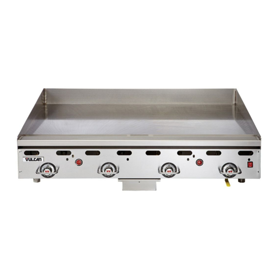
Heavy duty gas griddle
Hide thumbs
Also See for 924RX:
- Installation & operation manual (51 pages) ,
- Installation and operation manual (15 pages) ,
- Replacement parts catalog (9 pages)
Table of Contents
Advertisement
948RX
This Manual is prepared for the use of trained Vulcan Service
Technicians and should not be used by those not properly qualified.
This manual is not intended to be all encompassing. If you have not
attended a Vulcan Service School for this product, you should read,
in its entirety, the repair procedure you wish to perform to
determine if you have the necessary tools, instruments and skills
required to perform the procedure. Procedures for which you do not
have the necessary tools, instruments and skills should be
performed by a trained Vulcan Service Technician.
The reproduction, transfer, sale or other use of this Manual, without
the express written consent of Vulcan, is prohibited.
This manual has been provided to you by ITW Food Equipment
Group LLC ("ITW FEG") without charge and remains the property
of ITW FEG, and by accepting this manual you agree that you will
return it to ITW FEG promptly upon its request for such return at
any time in the future.
For additional information on Vulcan-Hart Company or to locate an authorized parts
and service provider in your area, visit our website at www.vulcanhart.com.
A product of VULCAN-HART
SERVICE MANUAL
HEAVY DUTY GAS GRIDDLES
MODELS
924RX
936RX
948RX
960RX
972RX
MSA24
MSA36
MSA48
MSA60
MSA72
LOUISVILLE, KY 40201-0696
F25383 (510)
Advertisement
Table of Contents

Related Manuals for Vulcan-Hart 924RX


Summary of Contents for Vulcan-Hart 924RX
- Page 1 ITW FEG promptly upon its request for such return at any time in the future. For additional information on Vulcan-Hart Company or to locate an authorized parts and service provider in your area, visit our website at www.vulcanhart.com.
-
Page 2: Table Of Contents
TROUBLESHOOTING ..............15 © VULCAN 2010... -
Page 3: General
GENERAL GENERAL The griddle and its parts are hot. Use care when operating, cleaning or servicing the griddle. monitored by thermocouples and pilot safety valves. INTRODUCTION If the pilot goes out, the safety valve will shut-off the gas supply to the pilot and main burners. In the event This Service Manual covers specific service of a failure of the electronic ignition system, it is information related to the models listed on the front... -
Page 4: Tools
GENERAL TOOLS • Standard set of hand tools. • VOM with A/C current tester (any quality VOM with a sensitivity of at least 20,000 ohms per volt can be used). • Temperature tester (thermocouple type). • U-Tube or Digital Manometer. •... -
Page 5: Removal And Replacement Of Parts
REMOVAL AND REPLACEMENT OF PARTS REMOVAL AND REPLACEMENT OF PARTS Back Panel COVERS AND PANELS Front Panel NOTE: It will be necessary to remove the back panel Turn all thermostats to off position, loosen set when changing a burner or to remove excessive screw securing thermostat knobs and pull off grease build up from flue area. -
Page 6: Electric Igniter (900Rx)
REMOVAL AND REPLACEMENT OF PARTS Measure distance between manifold pipe and ELECTRIC IGNITER (900RX) valve for reassembly later. NOTE: Ignition wires must be routed in front of valves as shown to prevent them from touching hot heat shield. Remove FRONT PANEL. Push tab to release igniter from frame and pull out of unit. - Page 7 REMOVAL AND REPLACEMENT OF PARTS Remove screws securing thermostat mounting 10. Carefully insert orifice into burner and secure bracket to frame. thermostat mounting bracket to frame. Pull capillary tube out from underneath griddle plate. Transfer fittings from old thermostat to new 11.
-
Page 8: Burner
REMOVAL AND REPLACEMENT OF PARTS BURNER PILOT, THERMOCOUPLE ASSEMBLY Remove FRONT PANEL. From underneath the front of the griddle, remove screw securing pilot assembly bracket. Remove FRONT PANEL and REAR PANEL. Disconnect gas supply at griddle. Remove screw securing burner to wall. VIEW FROM REAR OF UNIT TO SEE PARTS Carefully lift to disengage bracket from slot and work assembly down to access parts. -
Page 9: Service Procedures And Adjustments
SERVICE PROCEDURES AND ADJUSTMENTS SERVICE PROCEDURES AND ADJUSTMENTS Set thermostats to 350°F and allow to stabilize. CALIBRATION Record the temperature tester readouts for Level each zone for 3 cycles. The griddle must be level (side-to-side and Temperature Temperature Turn-Off + front-to-back) during operation to ensure proper Tester turn-off Tester turn-on... -
Page 10: Pilot Adjustment
SERVICE PROCEDURES AND ADJUSTMENTS GAS PRESSURE MEASUREMENT Turn the gas supply off at a manual shutoff valve. Remove the control panel. Remove the pressure tap plug and attach manometer. Turn gas back on. Never adjust the screw in the center of the thermostat shaft. -
Page 11: Burner Adjustment
SERVICE PROCEDURES AND ADJUSTMENTS The supply pressure (upstream of the regulator) should be 7-9” W.C. for natural gas and 11-12” W.C. for propane gas. At no time should the griddle be connected to supply pressure greater than ½ psig (3.45 kPa) or 14” W.C. Graphic shows pressure plug location. -
Page 12: Thermocouple Test
SERVICE PROCEDURES AND ADJUSTMENTS Verify thermocouple output voltage. THERMOCOUPLE TEST If 25 - 35 millivolts is measured, the Unscrew thermocouple fitting from safety valve. thermocouple is functioning properly. If less than 17 millivolts is measured, install a replacement thermocouple. Remove test adapter. Install thermocouple test adapter finger tight plus a quarter turn. -
Page 13: Electrical Operation
ELECTRICAL OPERATION ELECTRICAL OPERATION ELECTRICAL DIAGRAM Page 13 of 16 F25383 (510) - Page 14 ELECTRICAL OPERATION F25383 (510) Page 14 of 16...
-
Page 15: Troubleshooting
TROUBLESHOOTING TROUBLESHOOTING SYMPTOMS POSSIBLE CAUSES No spark to ignite pilot gas. Power cord unplugged. Igniter switch malfunction. Shorted electrode on ignitor. Ignitor cable malfunction. Interconnecting wiring malfunction. Electric Igniter Module malfunction. Sparks but gas does not ignite. Service gas valve closed. Gas supply not purged of air. - Page 16 TROUBLESHOOTING F25383 (510) Printed in USA...
Need help?
Do you have a question about the 924RX and is the answer not in the manual?
Questions and answers