Advertisement
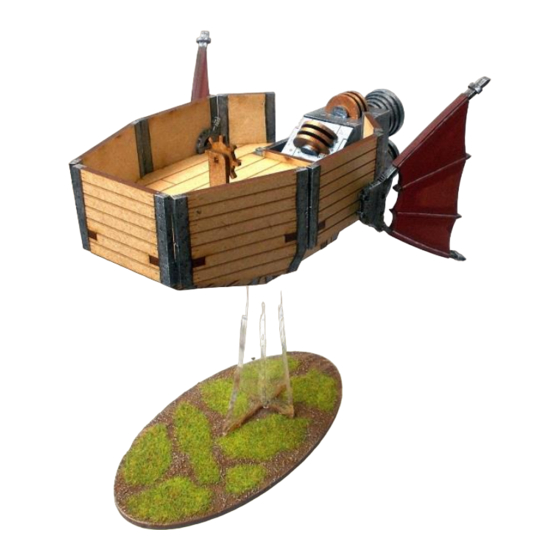
Shako Rocket Tosen
B28-VSF-007
Please read these instructions fully before starting construction.
PVA or equivalent glue will be required to stick sections together.
Sand paper can be used to gently clean any joints.
A sharp modelling knife will be required to remove sections from the sprue. Please use knives with due care and remember
to cut away from yourself at all times.
During the construction of this model, you may find it convenient to use pegs / elastic bands to hold pieces in place while
you allow glue to dry.
Note – For this model you may find it easier to build sub-assemblies and paint them before attaching them to the model.
Two examples of these are the engine module and sails.
We also painted all the metalwork on the side and hull panels prior to assembly.
First construct two rocket bells from the pieces
shown above.
Place the largest ring over the supports, aligning
the flat portions of the inner ring with the
supports. Repeat for the other rings.
Glue the semi-circles into the central space as
shown.
Start by glueing the internal supports together.
The sides of the rocket are formed from these
pieces.
The axle is made from these pieces.
Advertisement
Table of Contents

Related Manuals for BLOTZ Shako Rocket Tosen


Summary of Contents for BLOTZ Shako Rocket Tosen
- Page 1 Shako Rocket Tosen B28-VSF-007 Please read these instructions fully before starting construction. PVA or equivalent glue will be required to stick sections together. Sand paper can be used to gently clean any joints. A sharp modelling knife will be required to remove sections from the sprue. Please use knives with due care and remember to cut away from yourself at all times.
- Page 2 The rear plate plus the two rockets. Glue them together as shown. Glued together as above. All the pieces of the rocket section. Place the axle through the holes in the sides, then Glue the rest of the pieces into place. attach the sides to the rear plate as shown above.
- Page 3 Glue the two outer “clips” into position. The two completed front sails. Take the pieces shown and glue them together Make sure the top of the back plate is at the same with the engine going between each long hull level as the rear girders.
- Page 4 Attach the two cover plates on both side of the Glue the two levers twowards the rear of the side engine axle. hull plates hiding the wing support holes. The ships wheel is formed from these three Glue them together as shown. pieces.
Need help?
Do you have a question about the Shako Rocket Tosen and is the answer not in the manual?
Questions and answers