Advertisement
Quick Links
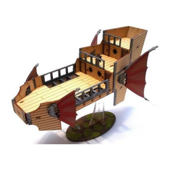
Onaga Rocket Kohaya
B28-VSF-006
Please read these instructions fully before starting construction.
PVA or equivalent glue will be required to stick sections together.
Sand paper can be used to gently clean any joints.
A sharp modelling knife will be required to remove sections from the sprue. Please use knives with due care and remember
to cut away from yourself at all times.
During the construction of this model, you may find it convenient to use pegs / elastic bands to hold pieces in place while
you allow glue to dry.
Take the sides, struts and support plates (shown
above) from the sprue.
The same pieces shown from the other side –
showing the position of the notch.
Take the main deck and "wall" from the sprue.
Glue the "wall" into position. Allow to dry.
Stick the support plates to the reverse side of a side
piece as shown above. The arrow should point
towards the front of the ship.
Attach the other side piece and slide the support
struts into place.
Attach the deck using the holes / lugs provided.
Take the base plate and prow sections from the
sprue.
Advertisement

Subscribe to Our Youtube Channel
Related Manuals for BLOTZ Onaga Rocket Kohaya


Summary of Contents for BLOTZ Onaga Rocket Kohaya
- Page 1 Onaga Rocket Kohaya B28-VSF-006 Please read these instructions fully before starting construction. PVA or equivalent glue will be required to stick sections together. Sand paper can be used to gently clean any joints. A sharp modelling knife will be required to remove sections from the sprue. Please use knives with due care and remember to cut away from yourself at all times.
- Page 2 Turn the model over and attach the base plate as Glue the prow pieces into place. shown above. Take the middle and upepr deck sections plus the ..and glue them into position. top “wall”…. Take the pieces shown above from the sprue. Attach them to the model as shown, with etched detail facing outwards.
- Page 3 Take the stern pieces. And glue them into place. Each rocket is formed from the pieces shown Start by glueing the internal supports together. above. Place the largest ring over the supports, aligning The sides of the rocket are formed from these the flat portions of the inner ring with the pieces.
- Page 4 Glued together as above. All the pieces of the rocket section. Place the axle through the holes in the sides, then Glue the rest of the pieces into place. attach the sides to the rear plate as shown above. The washers… Place three on each end of the axle.
- Page 5 The rear sails are formed from these pieces. As with the front sails, glue the ain pieces back to back then attach the supports – note these slope down towards to the front of the sail. Glue the brackets into place. The ships wheel is formed from these three pieces.
- Page 6 The completed model.
Need help?
Do you have a question about the Onaga Rocket Kohaya and is the answer not in the manual?
Questions and answers