Table of Contents
Advertisement
Quick Links
Advertisement
Table of Contents
Troubleshooting

Subscribe to Our Youtube Channel
Related Manuals for CareFusion Alaris 8210 Series


Summary of Contents for CareFusion Alaris 8210 Series
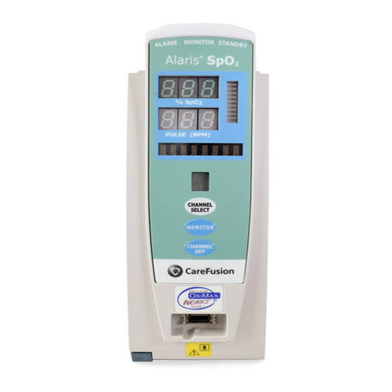
- Page 1 Technical Service Manual ® Alaris Modules ® 8210 Series (Nellcor Technology) ® 8220 Series (Masimo Technology) ® Supports: Guardrails Suite (v7) Guardrails ® Suite MX (v8) December 2010 % SpO 2 PULSE (BPM) CHANNEL SELECT MONITOR CHANNEL ® Alaris Products...
- Page 2 General Contact Information CareFusion San Diego, California http://www.carefusion.com/alaris Customer Advocacy - North America Clinical and technical feedback. Phone: 888.876.4287 E-Mail: CustomerFeedback@carefusion.com Technical Support - North America Maintenance and service information support; troubleshooting. United States: Canada: Phone: Phone: 888.876.4287 800.387.8309 Customer Care - North America Instrument return, service assistance, and order placement.
-
Page 3: Table Of Contents
TABLE OF CONTENTS Chapter 1 - General Information Introduction ....................................... Features ......................................Alarms, Errors, Messages ............................... Chapter 2 - Checkout and Configuration Introduction ....................................... New Instrument Checkout ............................... Configuration Options and Setup - General ........................ 2.3.1 Configuration Notes ..................................2.3.2 Factory Default Setting ................................ - Page 4 TABLE OF CONTENTS Chapter 5 - Corrective Maintenance (Continued) ® 5.2.8 Removing Masimo Board and Power Supply Board Assemblies 5-10 ........... 5.2.9 Removing IUI Bracket Strap and Bracket 5-11 ........................5.2.10 Removing Display Board Assembly 5-12 ..........................5.2.11 Removing Status Indicator Lens 5-13 ............................
-
Page 5: Chapter 1 - General Information
CAUTION under warranty, it must be serviced only by Any attempt to service this product by anyone CareFusion authorized service personnel. other than an authorized CareFusion Service Reference the "Warranty" and "Service Representative, while the product is under ® Information" sections in the Alaris System warranty, may invalidate the warranty. -
Page 6: Defined Terms
GENERAL INFORMATION FEATURES (Continued) • 8220 Series: Signal Extraction ® ® Technology ) for accurate readings under extreme conditions (such as, low perfusion and motion). ® Reference the Alaris System for a list of features and definitions. Table 1-1. Defined Terms The following table identifies the defined terms used throughout this document for certain trademarked products and product features. -
Page 7: Chapter 2 - Checkout And Configuration 2.1 Introduction
Contact CareFusion authorized service personnel if the instrument has physical damage, fails to satisfactorily pass the startup sequence, fails a self test, or continues to alarm. -
Page 8: Configuration Options And Setup - General
CHECKOUT AND CONFIGURATION CONFIGURATION OPTIONS AND 2.3.3 Configuration Setup Notes SETUP - GENERAL (Continued) • Pressing soft key while in a EXIT System Configuration - Module screen 2.3.1 Configuration Notes (Continued) immediately powers system down, with no "Powering Down" display. •... -
Page 9: Alarm Limits
CHECKOUT AND CONFIGURATION CONFIGURATION SETUP (Continued) System Configuration - SPO2 2.4.1 Access System Configuration Options Adult alarm limits (Continued) %SPO2 HIGH %SPO2 Press Module soft key. To view SPO2 PULSE HIGH additional options, press PAGE DOWN PULSE soft key. >Select Parameter Limit System Config - SPO2 1 of 2 CONFIRM Adult alarm limits... - Page 10 CHECKOUT AND CONFIGURATION CONFIGURATION SETUP (Continued) Select Adult or Neonatal by pressing applicable soft key. 2.4.2 Alarm Limits (Continued) • Following display represents To accept change, press key. ENTER Neonatal alarm limits but same procedure is used for confi guring •...
-
Page 11: Satseconds Limits (8210 Series)
CHECKOUT AND CONFIGURATION CONFIGURATION SETUP (Continued) • Selectable options are Off, or seconds. 2.4.4 Pulse Beep Volume (Continued) To accept settings, press soft CONFIRM To increase volume, press Louder key. soft key until desired volume level is attained. To turn off pulse beep entirely, 2.4.6 Saturation Averaging Time ( Series) 8220... - Page 12 CHECKOUT AND CONFIGURATION THIS PAGE INTENTIONALLY LEFT BLANK ® Alaris Modules Technical Service Manual...
-
Page 13: Chapter 3 - Preventive Maintenance
Chapter 3 – PREVENTIVE MAINTENANCE INTRODUCTION WARNING Perform regular and preventive maintenance Failure to perform regular and preventive inspections to ensure that the Module maintenance inspections may result in improper remains in good operating condition: instrument operation. • Perform regular inspections before each use. - Page 14 PREVENTIVE MAINTENANCE THIS PAGE INTENTIONALLY LEFT BLANK ® Alaris Modules Technical Service Manual...
-
Page 15: Chapter 4 - Principles Of Operation
Chapter 4 – PRINCIPLES OF OPERATION INTRODUCTION This chapter describes the Module principles of operation. Reference the PC Unit / Pump Module Series) Technical Service Manual 8000 8100 for Alaris ® System principles of operation. GENERAL INFORMATION Module operation is based on the principles of pulse oximetry. -
Page 16: 8220 Series (Masimo Technology)
PRINCIPLES OF OPERATION 8210 series (Nellcor Technology) ), the calculated value may differ from the measurement of the (Continued) Module. This usually occurs because the By doing so, it focuses on light absorption calculated saturation was not appropriately by pulsatile arterial blood, eliminating the corrected for the effects of variables that effects of nonpulsatile absorbers (such as, shift the relationship between... -
Page 17: Introduction
Return circuit boards to an authorized CareFusion Service Center for repair. Attempting circuit board CAUTION repairs voids all warranties. devices are sensitive to static electrical... -
Page 18: Required Materials, Supplies And Tools
CORRECTIVE MAINTENANCE DISASSEMBLY / REASSEMBLY CAUTION To avoid the risk of an electrical hazard or To disassemble the instrument, follow damage to the instrument circuitry, do not the steps in order from the first step. To spray fluids directly onto the instrument or reassemble, perform the steps in their allow fluids to enter the instrument. - Page 19 CORRECTIVE MAINTENANCE DISASSEMBLY / REASSEMBLY (Continued) 5.2.1 Removing Latch Assembly and Feet During Reassembly: Apply thin layer of Dow Corning Molykote Remove screws ( ) attaching Latch (or equivalent) silicone grease to Feet. Assembly to bottom of Rear Case. Remove Latch Assembly components. NOTE: The feet press-fi...
- Page 20 CORRECTIVE MAINTENANCE DISASSEMBLY / REASSEMBLY (Continued) 5.2.2 Removing IUI Connector Assemblies • To install Right Connector Gasket, remove protective backing and adhere to and Rear Case Connector. Remove screws ( ) attaching each IUI • To install Left Connector Seal, position (left and right) to module.
- Page 21 CORRECTIVE MAINTENANCE DISASSEMBLY / REASSEMBLY (Continued) 5.2.3 Removing Frame Assembly • Align and engage display connectors ) with Power Supply Board and Logic Remove screws ( ) attaching Frame Board connectors. Assembly to Front Case Assembly. • Ensure Patient Board connector is Remove Bracket Strap screw.
- Page 22 CORRECTIVE MAINTENANCE DISASSEMBLY / REASSEMBLY (Continued) 5.2.4 Removing Patient Connector Board Assembly Use needle nose pliers to remove Christmas Tree Clip securing Patient Connector Board to Frame Assembly. Disconnect Patient Connector Board from on Power Supply Board. Christmas Tree Clip Patient Connector Board ®...
- Page 23 CORRECTIVE MAINTENANCE DISASSEMBLY / REASSEMBLY (Continued) 5.2.5 Removing Logic Board Assembly Use small diagonal cutters to lift and remove Snap Rivet from Logic Board. CAUTION Do not cut rivet. Remove Logic Board. Snap Rivet Logic Board ® Alaris Modules Technical Service Manual...
- Page 24 CORRECTIVE MAINTENANCE DISASSEMBLY / REASSEMBLY (Continued) 5.2.6 Removing Speaker During Reassembly: • Bundle excess speaker wires together Disconnect Speaker Connector from with a cable tie. on Power Supply Board. • Use modified Christmas Tree Clip (tip Use needle nose pliers to remove removed) in speaker mounting hole Christmas Tree Clips ( ) attaching...
- Page 25 CORRECTIVE MAINTENANCE DISASSEMBLY / REASSEMBLY (Continued) ® 5.2.7 Removing Nellcor Board and Remove Board from Frame Assembly. Power Supply Board Assemblies Remove screws ( 3) and associated , from either board, to separate Use small diagonal cutters to lift and washers board assemblies.
- Page 26 CORRECTIVE MAINTENANCE DISASSEMBLY / REASSEMBLY (Continued) ® 5.2.8 Removing Masimo Board and Remove Board from Frame Assembly. Power Supply Board Assemblies Remove screws ( 3) and associated , from either board, to separate Use small diagonal cutters to lift and washers board assemblies.
-
Page 27: Removing Iui Bracket Strap And Bracket
CORRECTIVE MAINTENANCE DISASSEMBLY / REASSEMBLY (Continued) 5.2.9 Removing IUI Bracket Strap and Bracket Slide Bracket Strap off Bracket. Slide Bracket off Frame. IUI Bracket Frame IUI Bracket Strap ® Alaris Modules 5-11 Technical Service Manual... -
Page 28: Removing Display Board Assembly
CORRECTIVE MAINTENANCE DISASSEMBLY / REASSEMBLY (Continued) 5.2.10 Removing Display Board Assembly During Reassembly: Bundle Backlight Cable, Keypad Harness, Remove screws ( ) attaching Display and Ground Wire together with a cable tie. Board to Front Case. Remove cable tie and disconnect Keypad Harness and Backlight Harness from Display Board. -
Page 29: Removing Status Indicator Lens
CORRECTIVE MAINTENANCE DISASSEMBLY / REASSEMBLY (Continued) 5.2.11 Removing Status Indicator Lens Remove screws ( ) attaching Status Indicator Lens to Front Case. Remove Status Indicator Lens. Status Indicator Lens Status Indicator Gasket ® Alaris Modules 5-13 Technical Service Manual... -
Page 30: Torque Values
CORRECTIVE MAINTENANCE Table 5-2. Torque Values Functional Application Item Description Torque Value FINAL ASSEMBLY Case Halves 6-32 x 12 in-lb IUI Connectors 6-32 x 12 in-lb FRONT CASE Display Board Assembly 4-40 x 6 in-lb Frame Assembly 4-40 x 6 in-lb Status Indicator Lens 4-40 x 6 in-lb... -
Page 31: Level Of Testing Guidelines
CORRECTIVE MAINTENANCE Table 5-3. Level of Testing Guidelines Use the Maintenance Software to perform testing. Tests to Perform = Required Blank = Not Applicable Repair/Replacement of: Display Board Front Case / Keypad Logic Board Board Patient Connector Board Power Supply Board Rear Case / IUI Connector ... - Page 32 CORRECTIVE MAINTENANCE THIS PAGE INTENTIONALLY LEFT BLANK ® 5-16 Alaris Modules Technical Service Manual...
-
Page 33: Chapter 6 - Troubleshooting
Chapter 6 – TROUBLESHOOTING INTRODUCTION Module alarms and displays an error message and/or error code when an operating malfunction occurs. Use the information in this chapter to help diagnose and correct technical problems. Use the Maintenance Software to perform applicable preventive maintenance, calibration, and verification procedures. -
Page 34: Technical Troubleshooting Guide
TROUBLESHOOTING Table 6-1. Technical Troubleshooting Guide Perform the steps in the order they are listed until the problem/fault is corrected. Before making a final diagnosis, visually inspect the Module for damage. Following repair, use the Maintenance Software to perform the required tests. Problem Remedy Display Problem... -
Page 35: Error Codes
TROUBLESHOOTING Table 6-2. Error Codes Reference the PC Unit / Pump Module ( Series) Technical Service Manual for details on 8000 8100 accessing the Maintenance Mode and viewing the Error Log. Error Code Subsystem Explanation Response Logic Board Logic Board failure. Cycle power. - Page 36 TROUBLESHOOTING THIS PAGE INTENTIONALLY LEFT BLANK ® Alaris Modules Technical Service Manual...
-
Page 37: Parts List
When a part number is not provided, that part is either not sold by CareFusion, is provided as part of a kit or higher assembly, or can only be replaced/repaired by CareFusion authorized service personnel. -
Page 38: Ordering Parts
ILLUSTRATED PARTS BREAKDOWN ORDERING PARTS Parts can be ordered by writing or calling CareFusion Customer Care (see "General Contact Information" at beginning of this manual). When requesting a part, provide the following information: • Product name and model number (for... -
Page 39: Parts List
ILLUSTRATED PARTS BREAKDOWN Table 7-1. Parts List NOTE: An "assembly" is a preassembled group of parts. A "kit" is a group of unassembled parts. Item Part Number Description 146980-000 Gasket, Status Indicator Front Case: 147716-001 8210 Series 146976-000 8220 Series 146978-000 Lens, Status Indicator 10011343... - Page 40 320930 Nellcor 3 Meter Directions for Use, English: ® Alaris System with Model 8000 PC Unit: 10014346 Electronic Copy 10014343 Printed Copy Maintenance Software: 10013678 Version 7 10013025 Version 8 Not sold by CareFusion. ® Alaris Modules Technical Service Manual...
-
Page 41: Front Case Assembly
ILLUSTRATED PARTS BREAKDOWN Figure 7-1. Front Case Assembly 2 PL 800 3 PL ® Alaris Modules Technical Service Manual... - Page 42 ILLUSTRATED PARTS BREAKDOWN Figure 7-2. IUI Bracket/Frame ® Alaris Modules Technical Service Manual...
-
Page 43: Masimo Spo Board - Power Supply Board Assembly
ILLUSTRATED PARTS BREAKDOWN ® Figure 7-3. Masimo Board - Power Supply Board Assembly 6 PL 3 PL 6 PL Power Supply Board Assembly ® Alaris Modules Technical Service Manual... - Page 44 ILLUSTRATED PARTS BREAKDOWN ® Figure 7-4. Nellcor Board - Power Supply Board Assembly 6 PL 3 PL 6 PL Power Supply Board Assembly 2 PL ® Alaris Modules Technical Service Manual...
-
Page 45: Frame Assembly - Logic Board View
ILLUSTRATED PARTS BREAKDOWN Figure 7-5. Frame Assembly - Logic Board View Excess speaker wire is bundled together and tied with Cable Tie (item 820). Tip is removed from Christmas Tree Clip (item 47) used in this location. Connected to Power Supply Board J6. -
Page 46: Frame - Front Case Assembly
ILLUSTRATED PARTS BREAKDOWN Figure 7-6. Frame - Front Case Assembly LED Assembly Cable (item 32), harness, and ground wire are bundled together and loosely tied with one Cable Tie (item 820). Ground wire is positioned between screw (item 800) and IUI Bracket Strap. 6 PL Frame Assembly To Display Board J4. -
Page 47: Iui Assembly
ILLUSTRATED PARTS BREAKDOWN Figure 7-7. IUI Assembly IUI Connector Kit, Right (item 120). IUI Connector Kit, Left (item 130). 4 PL IUI Connector Seal IUI Connector Gasket IUI Connector, Right IUI Connector, Left 4 PL 2 PL ® Alaris Modules 7-11 Technical Service Manual... -
Page 48: Rear Case Assembly
ILLUSTRATED PARTS BREAKDOWN Figure 7-8. Rear Case Assembly Latch Kit (item 90). Rubber Feet (item 75), Rear Case (item 85), and Silicon Tubing (item 80) are provided as separate items and as part of Rear Case Assembly Kit (item Latch Support 86). -
Page 49: Rear Label Locations
ILLUSTRATED PARTS BREAKDOWN Figure 7-9. Rear Label Locations Nameplate Label, which has a regulatory mark, is not field replaceable as an individual item. It is available only as part of Rear Case Assembly Kit (item 86). Labels (items 620 and 638) are provided as separate items and as part of Rear Case Assembly Kit (item 86). -
Page 50: Display Board Assembly
ILLUSTRATED PARTS BREAKDOWN Figure 7-10. Display Board Assembly This illustration is for board identification purposes only and does not represent the board's component layout. ® 7-14 Alaris Modules Technical Service Manual... -
Page 51: Logic Board Assembly
ILLUSTRATED PARTS BREAKDOWN Figure 7-11. Logic Board Assembly This illustration is for board identification purposes only and does not represent the board's component layout. ® Alaris Modules 7-15 Technical Service Manual... -
Page 52: Power Supply Board Assembly (8210 Series)
ILLUSTRATED PARTS BREAKDOWN Figure 7-12. Power Supply Board Assembly (8210 Series) This illustration is for board identification purposes only and does not represent the board's component layout. ® 7-16 Alaris Modules Technical Service Manual... -
Page 53: Power Supply Board Assembly (8220 Series)
ILLUSTRATED PARTS BREAKDOWN Figure 7-13. Power Supply Board Assembly (8220 Series) This illustration is for board identification purposes only and does not represent the board's component layout. ® Alaris Modules 7-17 Technical Service Manual... - Page 54 ILLUSTRATED PARTS BREAKDOWN THIS PAGE INTENTIONALLY LEFT BLANK ® 7-18 Alaris Modules Technical Service Manual...
- Page 56 ® ® ® ® Alaris and Guardrails are registered trademarks of CareFusion, Inc. or one of its subsidiaries. Masimo , SET , and Signal Extraction Technology ® are registered trademarks of Masimo Corporation. Nellcor ® is a registered trademark of Tyco Healthcare/Mallinckrodt, Inc. All other trademarks belong to their respective owners.
Need help?
Do you have a question about the Alaris 8210 Series and is the answer not in the manual?
Questions and answers