Salda Smarty 4X V User And Service Technical Manual
Source: salda.lt/en, vetter-lufttechnik.de
Advertisement
Quick Links
Advertisement

Related Manuals for Salda Smarty 4X V


Summary of Contents for Salda Smarty 4X V
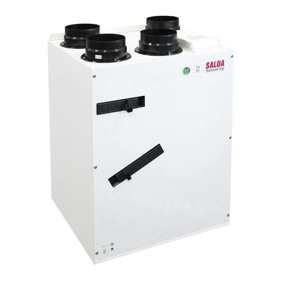
- Page 1 AHU WITH HEAT RECOVERY Smarty 4X V User‘s and service technical manual Smarty 4X V_P0115_AZ_0002...
- Page 2 Room CO transmitter installation recommendation concentration according to Pettenkofer limit 1.14 Event Log (History) Smarty 4X V 1.1 Version - Heater Control 1.15 System Versions and Running Time Smarty 4X V 1.2 Version - Heater Control 1.16 Air Flow Adjustment Connection of Supply and Extract Air Dampers 1.17 PID Controller Adjustment...
- Page 3 Smarty 4X V Warning – pay attention Additional information Stick the auxiliary label on the unit (on an easily accessible place) or on the dashed place of a technical manual in order to keep the important informa- 200003025238 TITLE 0.084 kW; 0.92 A; 230/50 V/Hz; ~1 0.085 kW;...
- Page 4 Smarty 4X V www.salda.lt...
- Page 5 Smarty 4X V Smarty 4X V are available in three versions: Optional heating elements *- only pre-heater or heater Duct based Duct based Air Pre- Air Heater Heater Mini MCB Premium Mini MCB Basic Advanced Not suitable for swimming pools, saunas and other similar facilities.
- Page 6 Smarty 4X V Unplug unit from mains before opening the door (discon- Description of remote control panel functions is provided in the remote or according to their testimony timer remote control. www.salda.lt...
- Page 7 Smarty 4X V Be sure the unit is disconnected from power source before performing any maintenance or repair. www.salda.lt...
- Page 8 Smarty 4X V www.salda.lt...
- Page 9 Smarty 4X V Prior to handover to the user, the pre-commissioning activities shall be performed to ensure proper operation of the automatic control system of the Unit shall be connected to the mains through the cur- After complete dismantling of the unit control auto-...
- Page 10 Smarty 4X V NOTE: Control board 2,5 mm miniMCB Exhaust air Supply air Outdoor air air Extract www.salda.lt...
- Page 11 Smarty 4X V Right side connection Left side connection Technical data Smarty 4X V 1.1 4X V 1.2 Exhaust air fan speed [min control input protection class Supply air fan speed [min control input protection class Automatic control integrated Pre-heater...
- Page 12 Smarty 4X V Operational limits Supply air V [l/s] 1400 Δ Pstat [Pa] P [W] 1200 1000 V [m /h] Exhaust air V [l/s] 1400 Δ Pstat [Pa] P [W] 1200 1000 V [m /h] V [l/s] 1200 Δ Pstat [Pa]...
- Page 13 Smarty 4X V Ø 160 mm Ø 150 mm G3/8 G3/8 406 mm 284 mm 599 mm 538 mm 113 mm 110 mm 386 mm Ø 150 mm/160 mm* 265 mm 110 mm 224 mm www.salda.lt...
- Page 14 Smarty 4X V Unit mounting on wall: www.salda.lt...
- Page 15 Smarty 4X V 400 mm The manufacturer does not assume any liability for personal injuries and property damage due to non- conformance with the provided instructions. www.salda.lt...
- Page 16 Smarty 4X V VIII Attention: Screwing force may not exceed 2 Nm. Note. Before every heating season the condensate tube shall be www.salda.lt...
- Page 17 Smarty 4X V System Modes: In Stand-by mode The Building protection mode Economy mode Comfort mode Start > End < System status Description Stand-by mode Building protection mode System operates in Building protection mode www.salda.lt...
- Page 18 Smarty 4X V Economy mode System operates in Economy mode Comfort mode System operates in comfort mode Emergency run System operates in emergency mode (for details refer to alarms section) Preparing Opening dampers Dampers are opened BOOST function activated BOOST function is active...
- Page 19 Smarty 4X V The function is activated by pressing ON and deactivated by pressing OFF button in the BOOST section, or by means of an external contactor (FANS Indication Alarms list www.salda.lt...
- Page 20 Smarty 4X V www.salda.lt...
- Page 21 Smarty 4X V and output, CO www.salda.lt...
- Page 22 Smarty 4X V of signals: 1.25.1 Filter Timer Settings 1.25.2 Air Filter Protections based on Pressure Relays (only Smarty 4X V 1.1) binations: of activated protection is indicated: www.salda.lt...
- Page 23 Smarty 4X V level Fan speed can be controlled by: 3P type damper control: www.salda.lt...
- Page 24 Smarty 4X V This protection is designed to protect the heat exchanger from the formation of ice inside because ice formations can damage the structure of the heat the outdoor air temperature, room air temperature and humidity) › Recirculation of outdoor and exhaust air...
- Page 25 Smarty 4X V Only either pre-heater or heater can be connected to MiniMCB basic board. Possible options of supplied air heaters in this system: Possible options of outdoor heaters: › exhaust air CO www.salda.lt...
- Page 26 Smarty 4X V Types of temperature sensors: Based on manufacturer set parameters If necessary, a complete description of miniMCB func- tions can be downloaded from www.salda.lt. www.salda.lt...
- Page 27 Smarty 4X V outdoor air supply air exhaust air extract air Separate power supply source Transmitter 2 Transmitter (EKA) MUTE*** MUTE*** TE** Stouch FLEX MCB Network Tinklas Gateway - Possibility to choose a direction of the drainage pipe Supply and exhaust air grilles...
- Page 28 Smarty 4X V outdoor air supply air exhaust air extract air Separate power supply source Transmitter 2 Transmitter (EKA) MUTE*** MUTE*** (EKA NIS/ EKA) TE** Stouch Stouch FLEX MCB Network Tinklas Gateway - Possibility to choose a direction of the drainage pipe...
- Page 29 Smarty 4X V www.salda.lt...
- Page 30 Smarty 4X V www.salda.lt...
- Page 31 Smarty 4X V www.salda.lt...
- Page 32 Smarty 4X V www.salda.lt...
- Page 33 Smarty 4X V www.salda.lt...
- Page 34 Smarty 4X V www.salda.lt...
- Page 35 Smarty 4X V www.salda.lt...
- Page 36 Smarty 4X V To ensure safe maintenance of the unit, it is necessary to Failure Cause Unit is not operating No supply voltages plug socket leakage relay is active (if installed by the in- staller) Air supply heater or heater is not operating or...
- Page 37 Smarty 4X V Fig. 1. Unit automation: Fig. 2. 1 2 3 4 5 6 1 2 3 4 1 2 3 4 5 6 1 2 3 4 5 6 1 2 3 4 5 6 7 8 1 2 3 4 5 6 7 8...
- Page 38 Smarty 4X V Connector Contactor No. Contactor name Functional block name miniMCB Not used 24VDC 24VDC_P STEP_B Bypass step motor control STEP_A 24VDC_P Supply fan speed RPM Extract fan speed RPM Fire protection input (NC) Electric Preheater automatic protection (NC)
- Page 39 Smarty 4X V A2-Extract air CO 24VDC Connector Contactor No. Contactor name Functional block name miniMCB 24VDC POWER L(L2)_2 DO2 (L(L2)_2) DO3 (L(L2)) DO4 (L(L2)) DO5 (L(L2)) Not used DO6 (L(L2)) DO6 (L(L2)) L(L2) www.salda.lt...
- Page 40 Smarty 4X V Connector Contactor No. Contactor name Functional block name miniMCB RS422_Z RS422_Y RS_GND 24VDC Connector Contactor No. Contactor name Functional block name miniEX1 24VDC 24VDC 24VDC www.salda.lt...
- Page 41 Smarty 4X V Connector Contactor No. Contactor name Functional block name miniEX1 Electric heater manual protection (NC) Electric heater automatic protection (NC) 1 2 3 4 5 6 Installation diagram. (EKA NIS/ EKA) Wiring diagram. www.salda.lt...
- Page 42 Smarty 4X V Supply air CO2 or RH (input 0-10VDC) Supply air CO Transmitter 2 Installation diagram. Wiring diagram. 1 2 3 Transmiter 1 Extract air CO Installation diagram. Wiring diagram. 1 2 3 4 5 6 7 8 www.salda.lt...
- Page 43 Smarty 4X V 5 0 c m i n . min. 60 cm max. 400m Where the channel CO transmitter is used: it must be installed in the extract air duct. Tool for drilling holes are required for its installation.
- Page 44 Smarty 4X V The electric heater can be controlled by: Installation diagram. Mini MCB Wiring diagram. max. 0,6kW; 2,6A; 230V EKA ... -1F EKA ... -1F www.salda.lt...
- Page 45 Smarty 4X V Installation diagram. Mini MCB Wiring diagram. EKA NIS ... -1F PE N L1 1f, 230VAC 1 2 3 4 When using the supply air heater, the supply air sensor (SS) shall be installed downstream the heater (or cool- ing, bend of the air transportation system.
- Page 46 Smarty 4X V Installation diagram Mini MCB Connection diagrams SP55 and SP56: plication service or on the FLEX MCB control panel Settings in the environment of the MB-Gateway WEB application service With the Stouch control panel, it is impossible to change the settings...
- Page 47 Smarty 4X V Settings with the FLEX MCB control panel When using the supply air heater, the supply air sensor (SS) shall be installed downstream the heater (or cool- ing, bend of the air transportation system. www.salda.lt...
- Page 48 Smarty 4X V Installation diagram. Wiring diagram. 4 3 2 1 230VAC 230VAC ON/OFF ON/OFF Wiring diagram. Position Purpose Wiring diagram. Working Alarm indication indication output output (START) (STOP) 1 2 3 4 www.salda.lt...
- Page 49 Smarty 4X V Wiring diagram. LED indication miniMCB miniEX1 LED2 LED3 LED4 MiniMCB status LED LED5 Communication line Transmit indication LED6 Communication line Receive indication 24V peripheral POWER ON indication www.salda.lt...
- Page 50 Smarty 4X V Electrical heater Electrical preheater Electrical preheater Electrical preheater Electrical preheater EKA 160-5.0-2f Electrical preheater Electrical preheater sensor sensor Channel humidity transmit- EKA NIS 160-5,0-2f S-RCO2-F2 S-KCO2 S-KFF-U Net module Duct smoke detector S-RFF-U-D-F2 rj45 cable MB Gateway...
- Page 51 Smarty 4X V Condensate pump Siphon band band band MAXI BLUE SET Siphon D20 MPL Z (optional) Legs Supply and extract air Remote control Smarty legs grating FLEX MCB EN WSG 160 www.salda.lt...
- Page 52 Smarty 4X V Damper Electric heater Control board Control board Smarty 4X V door Damper Heater* Mini MCB* Mini MCB Basic** Door Heat exchanger Fan** Fan* Fan* Fan** Temperature sensor 3 m www.salda.lt...
- Page 53 Smarty 4X V www.salda.lt...
- Page 54 Smarty 4X V www.salda.lt...
Need help?
Do you have a question about the Smarty 4X V and is the answer not in the manual?
Questions and answers