Nidec HVAC Drive H300 Step-By-Step Manual
Hide thumbs
Also See for HVAC Drive H300:
- User manual (323 pages) ,
- Step-by-step manual (42 pages) ,
- Quick startup and operation manual (13 pages)
Table of Contents
Advertisement
Diese Anleitung bietet Informationen für eine schnelle Inbetriebnahme eines einfachen Umrichter-Motor-Systems.
This guide provides a fast and simple start-up procedure for a basic drive and motor installation.
Bei aufwendigeren Systemen: Umfassende Betriebsanleitungen, Online-Videos und Hilfsmittel finden Sie unter
For help with more advanced installations: Comprehensive user guides, online videos and help tools can be
unserer Webadresse oder über den vorstehenden QR-Code.
accessed using the web address or QR code above.
EN
DE
Bitte lesen Sie die dem Umrichter beiliegende Sicherheitsdokumentation, bevor Sie den Umrichter montieren oder
Please read the safety information booklet supplied with the drive before installation or set-up.
in Betrieb nehmen.
It is essential to read Section 4.4 in the
Beim M300 ist unbedingt der Abschnitt 4.2 in der
to using the Safe Torque Off function in safety systems.
vorstehenden QR-Code hinzuzuziehen, um die Safe Torque Off-Funktion in Sicherheitssystemen zu verwenden.
Step By Step Guide
HVAC Drive H300
Frame sizes 3 to 12
www.controltechniques.com/support
H300 User Guide
using the web address or QR code above prior
Steuerung – Kurzanleitung
über die Webadresse bzw. den
Part Number: 0478-0654-01
Issue: 1
Advertisement
Table of Contents

Related Manuals for Nidec HVAC Drive H300


Summary of Contents for Nidec HVAC Drive H300
- Page 1 Step By Step Guide HVAC Drive H300 Frame sizes 3 to 12 www.controltechniques.com/support Diese Anleitung bietet Informationen für eine schnelle Inbetriebnahme eines einfachen Umrichter-Motor-Systems. This guide provides a fast and simple start-up procedure for a basic drive and motor installation.
-
Page 2: Table Of Contents
Contents Introduction ................. 2 STEP 1: Check the contents of the box ......4 STEP 2: Check model and voltage ........4 STEP 3: Mount the drive ............. 5 STEP 4: Select supply / motor cables and fuses ....7 STEP 5: Remove the finger guard breakouts .... -
Page 3: Introduction
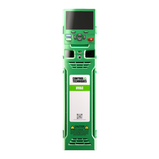
The following information is available for download at 'www.controltechniques.com/support': • H300 User Guide There is also a guided set-up contained in the software tool Connect available from: https://acim.nidec.com/drives/control-techniques/downloads • H300 Parameter Reference Guide Features of the drive Figure 1-1 Feature diagram for frame sizes 3 to 10... - Page 4 Figure 1-2 Feature diagram for frame size 11 11 13 1. Keypad connection 8. Control connections 2. Rating label 9. Communications port 3. Identification label 10. NV media card slot 4. Option module slot 1 11. Ground connections 5. Option module slot 2 12.
-
Page 5: Step 1: Check The Contents Of The Box
STEP 1: Check the contents of the box Check you have all the components and your drive has not been damaged during transportation. SAFETY KIT BOX* INFORMATION STEP BY STEP GUIDE * With frame size 7 to 11, surface mounting brackets are also supplied with the drive. STEP 2: Check model and voltage The model number can be found on the identification label on the top of the drive. -
Page 6: Step 3: Mount The Drive
STEP 3: Mount the drive The drive should be mounted in an ambient temperature range of - 20 °C to 55 °C (- 4 °F to 131 °F). Output current derating may be required at ambient temperatures > 40 °C (104 °F). Refer to the H300 User Guide (section 5). -
Page 7: Step 4: Select Supply / Motor Cables And Fuses
STEP 4: Select supply / motor cables and fuses The supply/motor cables and fuses or MCB’s used should follow the ratings provided in the table below: The voltage rating of fuses must be greater than or equal to the highest supply voltage of the system. Fuses: The AC supply to the drive must be installed with suitable protection against overload. - Page 8 Table 4-2 Frame 3 to 11 400 V drive ratings, cable sizes and fuse ratings (380 V to 480 V ±10 %) Nominal cable size Max. cont. Fuse Normal Duty input European current Max. Motor Model count. Input Output Input Output power power...
- Page 9 Table 4.3 Frame 12 400 V drive ratings, cable sizes and fuse ratings (380 V to 480 V ±10 %) Fuse (6 per Max. Nominal cable size (USA) Nominal cable size (European) mm drive) cont. input current Model Input Input Input 6 Input 12 Cable type...
- Page 10 Table 4.5 690 V drive ratings, cable sizes and fuse ratings (500 V to 690 V ±10 %) Max. Nominal cable size Fuse Normal Duty cont. European input Max. current Motor Model count. Input Output Input Output power power output @ 690 V @ 690 V Class...
-
Page 11: Step 5: Remove The Finger Guard Breakouts
STEP 5: Remove the finger guard breakouts Removing the finger-guard break-outs A: Size 3 to 11 B: Size 5 only C: Size 6 only D: Size 7 to 11 Place finger-guard on a flat solid surface and hit relevant break-outs with hammer as shown (1). For sizes 7 to 9 pliers can be used to remove the break-outs, grasp the relevant break-out with the pliers and twist it as shown (3). -
Page 12: Step 6: Wire The Drive Up
STEP 6: Wire the drive up This step covers connection of input power connection L1,L2, and L3 including the ground terminals, motor phases U V W and the control terminals. The tools required for this are terminal screwdriver, flat screwdriver, M7, M8, M10 and M17 sockets T20 and T25 driver. - Page 13 Power and Ground connections Connect the supply and motor connections using the cables and fuses quoted in the table shown in Step 4. Figure 6-1 Size 3 power and ground connections H300 Step By Step Guide...
- Page 14 Figure 6-2 Size 4 power and ground connections DC Connections Additional ground connection Ground connection AC Connections studs Optional EMC filter Optional line reactor Fuses Motor Optional ground Mains Supply connection supply ground H300 Step By Step Guide...
- Page 15 Figure 6-3 Size 5 power and ground connections H300 Step By Step Guide...
- Page 16 Figure 6-4 Size 6 power and ground connections H300 Step By Step Guide...
- Page 17 Figure 6-5 Size 7 and 8 power and ground connections (size 7 shown) H300 Step By Step Guide...
- Page 18 Figure 6-6 Size 9E, 10E power and ground connections H300 Step By Step Guide...
- Page 19 Figure 6-7 Size 9A power and ground connections H300 Step By Step Guide...
- Page 20 Figure 6-8 Size 11E power and ground connections H300 Step By Step Guide...
- Page 21 Figure 6-9 Power Module Frame 12 power connections Electrochemical corrosion of grounding terminals Ensure that grounding terminals are protected against corrosion i.e. as could be caused by condensation. WARNING The drive must be connected to the system ground of the AC supply. The ground wiring must conform to local regulations and codes of practice.
- Page 22 Control connections The control terminals are configured by default for the arrangement shown below: Figure 6-10 H300 control terminal connections Aux 24 V supply 0V common External 24 V supply Analog frequency/speed reference 1 & 2 0V common 4 - 20 mA Input 0V common Single ended...
- Page 23 Communications connections The drive offers a 2 wire EIA-485 serial interface located beneath the control terminals, see Figure 6-11 Location of the comms connector below. The drive supports the Modbus RTU, BACnet MSTP protocols. See Figure 6-4 for the connection details. Figure 6-11 Location of the comms connector Table 6-4 Serial communication port pin-outs Function...
- Page 24 Figure 6-12 KI-485 Adaptor Installation To install, align the KI-485 Adaptor and press gently in the direction shown until it clicks into position. To remove, reverse the installation instructions. IEC cable sizes assume Copper conductor, PVC insulation, Installation method B2 and ambient NOTE temperature of 40 °C (104 °F).
-
Page 25: Step 7: Use The Keypad
STEP 7: Use the keypad The keypad display provides information to the user regarding the operating status of the drive, alarms and trip codes. The keypad buttons provide a means for changing parameters, stopping and starting the drive, and the ability to perform a drive reset. Keypad key identifier 1. -
Page 26: Step 8: Run The Drive For The First Time In Hand Mode
Hand / Off / Auto Hand / Off / Auto functions are enabled if Pr 1.052 is set to a non-zero value, otherwise the keypad buttons are allocated as follows: • Blue - Forward/Reverse AUTO • Green - Run • - Reset When Hand / Off / Auto functions are enabled (Pr 1.052 set to either 1, 2 or 3), then the keypad buttons will be allocated as follows:... - Page 27 Ensure Pr 0.014 is Select Pr 11.031 and check Open Loop is selected set to Open-Loop M o t o r M o t o r T y p e T y p e Induction Induction Open-loop Control Mode Fixed Configure the motor •...
- Page 28 The drive is able to perform either a stationary or a rotating Autotune autotune. The motor must be at a standstill before an autotune is enabled. A rotating autotune should be used whenever possible so the measured value of power factor of the motor is used by the drive.
- Page 29 Set the Hand Mode The Drive's reference frequency by default is set to auto within Pr 1.052 at start up, and the Reference reference by default will come through Analog input terminal T5 (by default set to 4-20 mA) , frequency.
- Page 30 RFC - A Sensorless To run the H300 Drive in RFC-A mode will require a mode change as the factory defaults are set for Open Loop Induction Motor. Changing the operating mode Changing the operating mode returns all parameters to their default value, including the motor parameters.
- Page 31 Action Detail The drive is able to perform either a stationary or a rotating autotune. The motor must be at a standstill before an autotune is enabled. A stationary autotune will give moderate performance whereas a rotating autotune will give improved performance as it measures the actual values of the motor parameters required by the drive.
- Page 32 Run a Permanent-magnet motor in closed-loop sensorless (RFC-S) To run the H300 Drive in RFC-S mode will require a mode change as the factory defaults are set for Open Loop Induction Motor. Before powering up the drive open the Enable/ Safe Torque Off input T29, and all run signals, so that the drive powers up in the Inhibit State.
- Page 33 Saving parameters When changing a parameter in Menu 0, the new value is saved when pressing the Enter button to return to parameter view mode from parameter edit mode. If parameters have been changed in the advanced menus, then the change will not be saved automatically.
- Page 34 Configure If the Motor requires thermal protection the H300 Drives has the following Thermistor types Motor Thermal programmed within parameter P0.029 Analog Input 2 Thermistor Type. Protection. DIN44082 (Default) KTY84 PT100 PT1000 PT2000 NI1000 Parameter P0.027 Analog Input 2 Mode will need to be set to either of the following as required by the application.
- Page 35 Autotune he drive is able to perform either a stationary or a rotating autotune. The motor must be at a standstill before an autotune is enabled. A rotating autotune should be used whenever possible so the measured value of power factor of the motor is used by the drive. A rotating autotune will cause the motor to accelerate up to base speed in the direction...
- Page 36 Start the motor in Make sure it is safe to run the motor. Press the Green HAND button, the drive will start and Hand mode. the motor will accelerate to the hand speed reference which is nominally the minimum clamp frequency setting.
-
Page 37: Step 9: Running The Drive In Auto Mode
STEP 9: Running the drive in Auto mode This section gives guidance on how to get running in Auto mode . By default the drive is set via Pr1.052 to Auto (1). Action Detail Enable the drive Close the Enable or Safe Torque off input to the drive. O f f r p m Start the motor in... -
Page 38: Additional Information
Additional Information Restoring drive defaults Restoring parameter defaults by this method saves the default values in the drives memory. User security status (00.031) and User security code (00.030) are not affected by this procedure). Procedure 1. Ensure the drive is not enabled, i.e. terminal 29 is open or Pr 06.015 is OFF (0) 2. - Page 39 Parameter Range Default Description RFC-A RFC-S RFC-A RFC-S 00.014 Injection (0), Current (1), Current (2), (RFC-S RFC low 5.064 Current No Test (3), Current Step (4), Current (2) mode speed mode Current Only (5) only) 00.015 Low speed (RFC-S sensor-less 5.071 0.0 to 1000.0 % 100.0 %...
- Page 40 Parameter Range Default Description RFC-A RFC-S RFC-A RFC-S PID feedback 00.034 high trip 29.041 0.00 to 327.67 UU 0.00 UU threshold PID feedback 00.035 29.042 0.0 to 6553.5 s 5.0 s low delay PID feedback 00.036 29.043 Disabled (0), Threshold (1), Bandwidth (2) Disabled (0) low mode PID feedback...
- Page 41 Parameter Range Default Description RFC-A RFC-S RFC-A RFC-S No flow 00.056 29.070 0.0 to 3000.0 150.0 detection band No flow 00.057 detection 29.071 0.0 to 6553.5 s 5.0 s delay No flow 00.058 setpoint 29.072 0.0 to 6553.5 s 1.0 s settling delay No flow 00.059...
- Page 42 Parameter Range Default Description RFC-A RFC-S RFC-A RFC-S None (0), Active (1), Card Slot 1 (2), Card Slot 2 (3), Card Slot 3 (4), Card Slot 4 (5), Card Product (6), NV Media Card User Prog (7), Card Busy (8), 00.074 Card Action 11.078...
-
Page 43: Ul Information
Appendix A UL information UL file reference These products are cUL Listed to Canadian and US requirements. UL file reference is: NMMS/7 E171230. Products that incorporate the Safe Torque Off (STO) function are Certified for Functional Safety. UL file reference: FSPC E171230. Operating environment Pollution Degree Products must be installed in a Pollution Degree 2 environment or better (dry, non-conductive... - Page 44 In this configuration, the unit is mounted sideways with the side panel against the mounting surface. A Tile Mounting Kit is available but must be ordered separately. Terminal Torque Torque settings are specified in relevant sections of this guide. Electrical Installation Overvoltage category Drives have been evaluated for OVC III Branch circuit Protection...
- Page 45 A.13 Transient Surge Suppression Frames sizes 7 & 8 – 575 V ratings Transient surge suppression shall be installed on the line side of this equipment and shall be rated to 575 Vac (phase to ground), 575 Vac (phase to phase), suitable for overvoltage category III, and shall provide protection for an impulse withstand voltage peak of 6 kV and a clamping voltage of maximum 2400 V.
- Page 46 A.18 Modular / group / parallel installation Supply wiring When used in modular drives/group / parallel installation applications the supply wires are not to be larger than 125 % of full load current of the device ratings CSA (Canadian Standards Authority) approval Frame sizes 9 to 11 are not certified for CSA approval when used in a modular / parallel setup.
- Page 47 Company information Nidec Control Techniques Limited. Registered Office: The Gro, Newtown, Powys SY16 3BE. Registered in England and Wales. Company Reg. No. 01236886. Moteurs Leroy-Somer SAS. Headquarters: Bd Marcellin Leroy, CS 10015, 16915 Angoulême Cedex 9, France. Share Capital: 65 800 512 €, RCS Angoulême 338567258.
Need help?
Do you have a question about the HVAC Drive H300 and is the answer not in the manual?
Questions and answers