
Subscribe to Our Youtube Channel
Related Manuals for FuzzDog Mutant Fuzz


Summary of Contents for FuzzDog Mutant Fuzz
- Page 1 Mutant Fuzz Regulus VIII Fuzz with mods Contents of this document are ©2015 Pedal Parts Ltd. No reproduction permitted without the express written permission of Pedal Parts Ltd. All rights reserved.
- Page 2 Important notes If you’re using any of our footswitch daughterboards, DOWNLOAD THE DAUGHTERBOARD DOCUMENT • Download and read the appropriate build document for the daughterboard as well as this one BEFORE you start. • DO NOT solder the supplied Current Limiting Resistor (CLR) to the main circuit board even if there is a place for it.
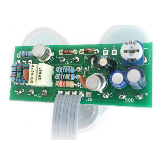
- Page 3 Schematic Q1-2 BC109* 100n 470p D1-2 1N4148 10u elec 1N4001 47u elec 2u2 elec BODY** 100KA 100KB 2K2 (CLR) 4K7 Trim CLIP** *Other NPN transistors can be used. Experiment. 2N3904 and 2N3565 work well. **BODY and CLIP are optional. If you prefer to keep to the original do the following: TO OMIT BODY TO OMIT CLIP •...
- Page 4 The power and signal pads on the PCB conform to the FuzzDog Direct Connection format, so can be paired with the appropriate daughterboard for quick and easy offboard wiring. Be very careful when soldering the diodes, LED and transistors. They’re very sensitive to heat. You should use some kind of heat sink (crocodile clip or reverse action tweezers) on each leg as you solder them.
- Page 5 Test the board! Check the relevant daughterboard document for more info before you undertake this stage. UNDER NO CIRCUMSTANCES will troubleshooting help be offered if you have skipped this stage. No exceptions. Once you’ve finished the circuit it makes sense to test is before starting on the switch and LED wiring.
- Page 6 Wire it up - DC only version (if using a daughterboard please refer to the relevant document) BOARD BOARD INPUT BOARD BOARD BOARD BOARD LED+ BOARD BOARD This circuit is standard, Negative GND. Your power supply should be Tip Negative / Sleeve Positive. That’s the same as your standard pedals (Boss etc), and you can safely daisy-chain your supply to this pedal.
- Page 7 BOARD BOARD BOARD LED+ BOARD Just because the BOARD FuzzDog enclosure BATTERY won’t take a battery, there’s nothing stopping you using a bigger box. This circuit is standard, Negative GND. Your power supply should be Tip Negative / Sleeve Positive. That’s the same as your standard pedals (Boss etc), and you can safely daisy-chain your supply to this pedal.
- Page 8 3 mm This template is a rough guide only. You should ensure correct marking of your enclosure before drilling. You use this template at your own risk. Pedal Parts Ltd can accept no responsibility for incorrect drilling of enclosures. FuzzDog.co.uk...
Need help?
Do you have a question about the Mutant Fuzz and is the answer not in the manual?
Questions and answers