Table of Contents
Advertisement
Advertisement
Table of Contents

Subscribe to Our Youtube Channel
Summary of Contents for Magneti Marelli Clima-Tech Plus
- Page 1 Clima-Tech Plus / Hd Evolution User’s Manual 007950015110 Magneti Marelli Aftermarket Spółka z.o.o. Plac Pod Lipami 5, 40-476 Katowice Tel.: + 48 (032) 6036107, Faks: + 48 (032) 603-61-08 e-mail: checkstar@magnetimarelli.com www.magnetimarelli-checkstar.pl...
- Page 2 • It is essential and an obligation of the user to use the device according to the manual and in line with the intended use specified in this document. MAGNETI MARELLI is not responsible for any use of this device that is not compliant with its intended purpose.
-
Page 3: Warranty Conditions
Magneti Marelli AfterMarket provides a warranty for “CLIMA-TECH TOP” cooling/air- conditioning installation diagnostic and maintenance station for 12 months from the purchase date as in the Magneti Marelli network sales document. Performing one or more warranty interventions during the warranty period doe not impact the warranty expiry period. -
Page 4: Device Description
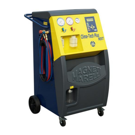
3 DEVICE DESCRIPTION 3.1 INTENDED PURPOSE CLIMA-TECH TOP is a fully automatic device designed for automotive air-conditioning installation maintenance. Recovery, recycling, emptying, oil injection, UV additive injection, installation charging and washing are the functions which can be performed by CLIMA-TECH TOP in a completely safe way and with maximum efficiency, exceptional in other similar equipment. - Page 5 CODE | DESCRIPTION logic board MEMORY CARD (OPTION) LOW PRESSURE VALVE HIGH PRESSURE VALVE BLUE HOSE 3000 RED HOSE 3000 LP QUICK CONNECTOR HP QUICK CONNECTOR D80 HP PRESSURE GAUGE D80 LP PRESSURE GAUGE PRESSURE SENSOR –1/20 BAR KPL DISTILLER OIL SEPARATOR FILTER COMPRESSOR...
- Page 6 ALPHA NUMERIC DISPLAY 16 x 2 A LED B LED ENTER LED C LED ENTER D LED E LED STOP/BACK LE STOP/BACK Down DOWN Decrease/enter parameters Increase/enter parameters ENTER Confirm function or menu STOP/BACK Select or exit menu S LED Power supply STOP/BACK A LED...
-
Page 7: Technical Specifications
Technical specifications 3.3.1 Main specifications Refrigerant: R134a Refrigerant electronic scales: Accuracy +/- 10 g Electronic vacuum meter: class 1.0 Low pressure / high pressure gauge: class 1.6 PLUS EVOLUTION Internal reservoir capacity: 12.4 l HD EVOLUTION Internal reservoir capacity: 27.2 l Maximum volume of R134a medium: 10 kg Maximum volume of R134a medium: HD version:... -
Page 8: Safety Rules
4 Safety The advanced technology adopted on design and production of CLIMA-TECH PLUS/HD EVOLUTION makes this unit extremely simple and reliable performing of all operations. The user is therefore not exposed to any risk provided that the general safety rules indicated below are followed and that the unit is properly used and maintained. - Page 9 4.2 Refrigerants handling instruction 4.2.1 Glossary • Refrigerant: cold-generating liquid to be only used in the device (e.g. R134a). • A/C system: air-conditioning system in a vehicle. • Device: CLIMA TECH EVOLUTION used for pumping out, cleaning and charging A/C system.
-
Page 10: Safety Devices
4.2.2 Refrigerant storage precautions Do not allow mixing various types of refrigerants removed from A/C systems. CLIMA TECH EVOLUTION is designed to support only R134a. To avoid mixing various refrigerants, it is recommended to store them in separate cylinders. Cylinders may not contain oil or other contaminants and the refrigerant they contain must be clearly indicated. -
Page 11: Operational Environment
It is forbidden to introduce any design changes in the above safety devices. 4.4 Operational environment • The device may only be operated in open or well-ventilated areas (minimum 4 air exchanges per hour). • The device is adapted to use in the following climate conditions: height up to 1000 m a.s.l., ambient temperature between +5°C and +40°C, humidity of up to 50% at +40°C. -
Page 12: Preparation For Operation
5 Use 5.1 Unpacking Remove the device from the packaging and make sure all equipment is included: operation manual memory card 2 R134a ball valves power supply cable 5.2 Storage Remove the device from the base. The device is fitted with 4 wheels;... - Page 13 5.4 Start-up Place the device with empty oil tanks on a level surface. Do not remove Connect or insert the memory card when the device device is on. power network, main switch (42) into ON (l) During the first start-up, select the language version from among the available ones. The default language is Italian SELECT LANGUAGE Polski...
- Page 14 After the operations described in the previous section, connect HP quick connector (red) of the device to the external tank using a supplied adapter. Open the coupling by twisting the valve clockwise. Open the valve on the external tank. There are two different tanks available: with and without suction pipe. tanks with suction pipe must be positioned straight to let the liquid refrigerant flow.
- Page 15 Confirm by pressing ENTER. Input desired refrigerant quantity XXXXX Push UP–DOWN to select quantity. Confirm by pressing ENTER Recovery in process maximum Quantity of recovered refrigerant quantity R134a XXXXX refrigerant to be gathered the internal tank is Filling of external tank finished 25 kg.
-
Page 16: Cylinder Bleeding
5.7 Cylinder bleeding Non-liquefied gasses draining valve (33) is calibrated at 12.8 bar for the standard version and for 16.8 bar for HD version; the valve was installed to allow gradual removal of non- liquefied gasses from the external tank. The valve is automatically energized by the system each time there is non-liquefied gas in the tank and their pressure is greater than the calibration pressure. -
Page 17: Error Messages
Maximum pressure was reached in the internal tank. Wait approx. 30 minutes before restarting the refrigerant recovery function. If this does not eliminate the problem, contact Magneti Marelli technical support. WARNING! Internal cylinder is full Maximum permitted quantity of refrigerant in the internal cylinder was reached. This value cannot be exceeded in any circumstances. -
Page 18: Functional Messages
Continue? Maximum anticipated recirculation/recovery time. Check the readings on the pressure gauges – if they show a pressure, the station may be damaged (contact Magneti Marelli technical representative), if they show no pressure, the vehicle A/C system or valve set may be leaking. - Page 19 Select ENTER to continue with the next phase. Select STOP/RETURN to return to standby mode. If there are no paper in the printer, lift the printer cover to secure the head. Use only paper available in Magneti Marelli Aftermarket offer. This message is accompanied with a warning sound. Select ENTER to exit.
-
Page 20: Description Of Operation
7 DESCRIPTION OF OPERATION In standby mode the device displays the quantity of refrigerant available. 7.1 Description of functions The station remembers selected A/C system filling parameters, linking them to the registration numbers entered in the database. When servicing vehicle with the same registration number again, it is possible to restore the parameters selected previously during maintenance. - Page 21 Space A DOWN ‘ & «...
- Page 22 8 PROGRAMS Connect LP-HP coupling (or one of the couplings). Open the flow to the coupling(s) by rotating appropriate wheels in the front panel of the station clockwise. LP-HP indicators (or one of the indicators, depending on the connection) indicate the pressure in both sections of the vehicle A/C system. Press ENTER in standby mode.
- Page 23 Connect HP/LP ■ □ Select using UP-DOWN buttons. Confirm by pressing ENTER. See chapter: Automatic program (without memory card), Automatic program (with a memory card), User program. 8.2 Automatic program (without memory card), When entering the program selection mode (see 9 PROGRAMS) the following menu appears: Auto Progr.
- Page 24 8.2.1 User’s vehicles Specify refrigerant weight □ Refrig. ■ Use UP-DOWN buttons to select the user’s vehicle. Confirm by pressing ENTER. > User’s vehicle 1 < User’s vehicle 2 Use UP-DOWN buttons to select the user’s vehicle. Confirm by pressing ENTER. If settings for the vehicle were previously input, the following screen will appear: Refrigerant qty g: XXXXX Vacuum:...
- Page 25 Name Vacuum Enter the correct value using UP-DOWN buttons. Confirm by pressing ENTER. Display will show the entered data. Refrigerant qty g: 700 Vacuum: Select ENTER to save the data. You will return to the user’s vehicles selection list. 8.3 Automatic program (with a memory card), When entering the program selection mode (see 9 PROGRAMS) the following menu appears: Auto Progr.
-
Page 26: User Program
> Alfa Romeo < Use UP-DOWN buttons to select the brand or go to user vehicles. Confirm by pressing ENTER. After selecting the brand you need to repeat all successive operations to confirm system filling parameters. Refrigerant qty g: XXXXX Vacuum: XX:XX Vacuum generation time is calculated based on the refrigerant quantity specified. - Page 27 Vacuum time A 20-minute vacuum phase will be suggested. Use UP-DOWN buttons to select the desired value. Confirm by pressing ENTER. System leaktightness control min. A 4-minute system leak test will be suggested at the end of vacuum phase. . Use UP-DOWN buttons to select the desired value.
- Page 28 8.5.2 Synchronized oil-UV feeding Manual Oil-UV ■ Synchro. Oil-Uv □ Use UP-DOWN buttons to select Synchronized Oil-UV. Confirm by pressing ENTER. ISO oil: 46 ■ 100 □ 150 □ Use UP-DOWN buttons to select oil ISO parameter. Confirm by pressing ENTER. Specify oil qty Use UP-DOWN buttons to select oil quantity to be introduced.
-
Page 29: Recovery Phase
9 RUNNING PROGRAMMED PHASES Open LP and HP valves on control panel or one of the valves, depending on the A/C system type. 9.1 Recovery phase Recycling phase This message appears on the display for a few seconds. Recycling in process – qty of recovered refrigerant g XXXXX Recovery phase stops automatically when the station detects that the system was... - Page 30 If synchronized oil-UV injection at the end of vacuum is selected, the following message will appear on the screen: Close LP valve Follow the instructions. Confirm with Enter. If Enter is not pressed at the end of vacuum phase, the device stops working and the message is displayed again.
- Page 31 Follow the instructions and press Enter. Filling phase in process XXXX If the pressure in the internal cylinder The data is displayed during filling phase. sufficient to perform filling, the procedure of stating the Filling phase finished remaining amount should be XXXXX performed through...
- Page 32 If memory card is not present or if No was selected, the following message is displayed: Disconnect HP/LP tubes from the system. Disconnect the device from the vehicle A/C system. Open LP and HP valves. Confirm with Enter. Warning! Refrigerant recovery from tubes This message confirms refrigerant recovery from tubes.
-
Page 33: Other Menu
10 OTHER MENU Press Enter in standby mode. Enter the number □ Other menu ■ Press Up or Down button to select Other menu field. Confirm with Enter. Filling in the internal cylinder. ■ Service □ Printing □ Diagnostics □ Diagnostics and Printing fields are available only if there is a memory card and/or printer present in the system. - Page 34 T.I.: °C __._ T.E.: °C __._ Enter the required values using Up and Down buttons. Confirm by pressing Enter each time after entering the value. Once all fields are filled in, confirm by pressing Enter for 3 seconds. The device will analyze the data. If a failure is suspected, the station shows a message specifying the failure and possible cause of the error.
- Page 35 Switch off the A/C system Follow the instructions. Confirm with ENTER. Disconnect LP tube from the system Follow the instructions. Confirm with ENTER. Wait! Refrigerant is recovered from the tubes The device recovers the refrigerant still present in the tubes. The display will show: Close LP/HP valves Follow the instructions.
- Page 36 The options below are available after selecting Other menu, provided the optional printer is fitted in the system. (007950014100). CLIMA-TECH PLUS/HD EVOLUTION: using the built-in printer allows to obtain a confirmation of performing each phase. The following functionalities are available: Repeat printing ■...
- Page 37 10.4 Service Enter password Enter the appropriate code using Up and Down buttons. Confirm with ENTER. 10.4.1 Changing language Enter code 03. Confirm with ENTER. SELECT LANGUAGE Italiano Use Up and Down buttons to select the desired language. Confirm with ENTER. 10.4.2 Resetting counters.
- Page 38 10.4.3 Restoring parameters Parameter restore option is available only if memory card is installed. Enter code 10. Confirm with ENTER. It is suggested that the Save data, data saved User models? memory card periodically. Confirm with ENTER. Transfer from mainboard ■...
-
Page 39: Maintenance
To restart the device, “activate” it only after opening the internal tank valves. 12 MAINTENANCE CLIMA-TECH PLUS/HD EVOLUTION is a highly reliable device, built using high quality components, using state-of-the-art technical solutions. Therefore, the maintenance activities are limited to a minimum, and their frequency is very low;... - Page 40 12.1 Vacuum pump oil change (code 007935090600) Vacuum pump oil must be changed frequently to assure the best performance of the pump. When it is time to change the vacuum pump oil, the display will show Al. Oil message. When changing the oil, follow the instructions below: it is forbidden to interfere with the components of the stations which are not specifically referred to in this section.
- Page 41 12.2 Replacing filters (code 007950013050) Drier filter should be replaced when its properties of absorbing the humidity from the recycled refrigerant are depleted. When it is time to replace the drier filter, the display will show AL.FiLt message. When replacing the filter, follow the instructions below: It is forbidden to interfere with the components of the stations which are not specifically referred to in this section.
- Page 42 12.3 Replacing memory card. The device is optionally equipped with database of vehicle models. The database is updated annually and once it is out of date, the device will show the following message New database version is available Press ENTER. Please contact dealer Press ENTER.
-
Page 43: Environmental Considerations
13 DISPOSAL 13.1 Environmental considerations This product may contain substances that may be harmful for the environment and health if not disposed of properly. Therefore, we provide you with the information below to avoid releasing such substances and to improve the usage of natural resources. Electrical and electronic equipment must not be mixed with regular municipal waste, but it should be disposed of to the specifically designated collection locations. - Page 44 DIAGRAM Magneti Marelli Aftermarket Spółka z.o.o. Plac Pod Lipami 5, 40-476 Katowice Tel.: + 48 (032) 6036107, Faks: + 48 (032) 603-61-08 e-mail: checkstar@magnetimarelli.com www.magnetimarelli-checkstar.pl...
Need help?
Do you have a question about the Clima-Tech Plus and is the answer not in the manual?
Questions and answers
Does anyone know how to calibrate the scale or a user manual for this model??? Thanks!
To calibrate the Magneti Marelli Plus scale, follow these steps:
1. Place the device on a level surface with empty oil tanks to ensure accurate scale operation.
2. Connect the device to a power source that matches the voltage, frequency, and power requirements specified on the rating plate.
3. Turn the main switch to the ON (I) position.
4. During start-up, the device will automatically perform a vacuum phase and calibration.
5. When prompted with "calibration ok!", press ENTER to confirm.
This completes the scale calibration process.
This answer is automatically generated
Boa tarde, Gostaria de reseta sem o tempo de manutenção teria como fazer isso
To reset the maintenance timer on a Magneti Marelli Clima-Tech Plus:
1. Navigate to the vacuum pump counter reset menu.
2. Press ENTER to confirm.
3. When the display shows "Hold ENTER button for 3 seconds! Counter reset," hold the ENTER button for 3 seconds.
4. Confirm the reset by pressing ENTER again.
This completes the maintenance timer reset.
This answer is automatically generated
Problème étalonnage code erreur ne peut plus étalonné
Calibration performed by an unauthorized service station is considered an issue with the Magneti Marelli Clima-Tech Plus. This is not covered under the warranty and may result in additional costs for the client.
This answer is automatically generated