Table of Contents
Advertisement
Quick Links
Instruction Manual
D100348X012
Fisher
2625, 2625SST, and 2625NS Volume
™
Boosters
Contents
. . . . . . . . . . . . . . . . . . . . . . . . . . . . . . . . .
. . . . . . . . . . . . . . . . . . . . . . . . . . . . . .
. . . . . . . . . . . . . . . . . . . . . . . . . . . . . . . . . .
. . . . . . . . . . . . . . . . . . . . . . . . . . . . . . . .
. . . . . . . . . . . . . . . . . . . . . . . . . . .
. . . . . . . . . . . . . . . . . . . . . . . . . . . . . . . . . .
. . . . . . . . . . . . . . . . . . . . . . . . . . . . . . . . . .
. . . . . . . . . . . . . . . . . . . . . . . . . . . . .
. . . . . . . . . . . . . . . . . . . . . . . . . . . . . . .
. . . . . . . . . . . . . . . . . . . . . . . . .
. . . . . . . . . . . . . . . . . . . . . . . . .
. . . . . . . . . . . . . . . . . . . . . . . . . . . . . . . . .
. . . . . . . . . . . . . . . . . . . . . . . . . . . . . . .
. . . . . . . . . . . . . . . . . . . . . . . . . . . . . . . . . . .
. . . . . . . . . . . . . . . . . . . . . . . . . . . . . . . . . . .
Introduction
Scope of Manual
This instruction manual provides installation, operation, maintenance, and parts information for Fisher 2625 Series
(2625, 2625SST, and 2625NS) volume boosters (figure 1). Refer to separate instruction manuals for information
regarding the valve body, actuator, and other accessories.
Do not install, operate, or maintain a 2625, 2625SST, or 2625NS volume booster without being fully
trained and qualified in valve, actuator, and accessory installation, operation, and maintenance. To
avoid personal injury or property damage, it is important to carefully read, understand, and follow all of
the contents of this manual, including all safety cautions and warnings. If you have any questions
regarding these instructions contact your
Description
The 2625 and 2625SST are certified for use in Safety Instrumented System (SIS) applications. Certification is by EXIDA
Consulting LLC, a global provider of functional safety and control system security. SIS certification is identified on the
product by the EXIDA logo on the 2625 nameplate.
www.Fisher.com
. . . . . . . . . . . . . . . . . . . . . . . .
. . . . . . . . . . . . . . . . . . . . . .
. . . . . . . . . . . . .
. . . . . . . . . . . . . . . . . .
. . . . . . . . .
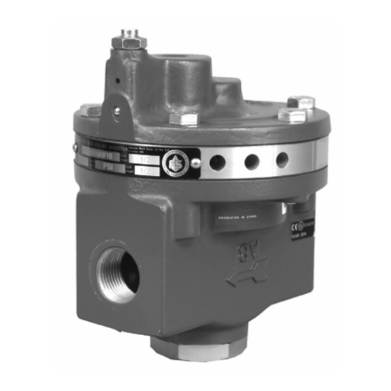
2625, 2625SST, and 2625NS Volume Booster
Figure 1. Fisher 2625 Volume Booster
1
1
1
2
2
4
5
5
6
7
7
7
8
8
8
9
10
11
11
12
Emerson sales office
before proceeding.
September 2022
Advertisement
Table of Contents

Related Manuals for Emerson Fisher 2625SST


Summary of Contents for Emerson Fisher 2625SST
-
Page 1: Table Of Contents
If you have any questions regarding these instructions contact your Emerson sales office before proceeding. Description The 2625 and 2625SST are certified for use in Safety Instrumented System (SIS) applications. -
Page 2: Specifications
Specifications for the 2625, 2625SST, and 2625NS volume booster are listed in table 1. Information for an individual unit as it comes from the factory appears on the product nameplate. Educational Services Emerson Automation Solutions Educational Services - Registration Phone: +1-800-338-8158 E-mail: education@emerson.com... - Page 3 Instruction Manual 2625, 2625SST, and 2625NS Volume Booster D100348X012 September 2022 Table 1. Specifications Port Diameters Maximum Flow Coefficients Supply Port: J 9.5 mm (0.375 inch) or J 12.7 mm See table 2 (0.5 inch) Exhaust Port: J 2.4 mm (0.094 inch) , J 9.5 mm Connections (0.375 inch) or J 12.7 mm (0.5 inch)
-
Page 4: Installation
Instruction Manual 2625, 2625SST, and 2625NS Volume Booster September 2022 D100348X012 Table 2. Maximum Flow Coefficients PORT SIZE COMBINATIONS SUPPLY PORT COEFFICIENTS EXHAUST PORT COEFFICIENTS Supply Port Exhaust Port Inch Inch 0.094 3.74 0.23 0.375 0.375 3.74 2.29 12.7 3.74 3.40 0.094 4.98... -
Page 5: Mounting
Instruction Manual 2625, 2625SST, and 2625NS Volume Booster D100348X012 September 2022 Mounting The volume booster is typically nipple‐mounted between the pneumatic supply source and the actuator, and may be used with piston or diaphragm actuators. Many actuators require larger casing or cylinder connections and modifications to allow the booster to deliver the higher volume output. -
Page 6: Diagnostic Connections
Instruction Manual 2625, 2625SST, and 2625NS Volume Booster September 2022 D100348X012 Figure 3. Typical Installations OPTIONAL POSITIONER OUTPUT DIAGNOSTIC (TOP CYL) POSITIONER CONNECTION VOLUME BOOSTER INPUT SIGNAL SUPPLY PIPE NIPPLE 67D, 67DR, OR MR95H PIPE TEE PIPE BUSHING BODY VOLUME BOOSTER BODY PROTECTOR ACTUATOR POSITIONER OUTPUT... -
Page 7: Supply Pressure
Instruction Manual 2625, 2625SST, and 2625NS Volume Booster D100348X012 September 2022 Supply Pressure Supply pressure must be clean dry air or noncorrosive gas. A high capacity filter, such as the 262K is recommended for use with the 2625 volume booster. NOTICE Use a clean, dry, oil‐free air supply with instruments containing EPDM components. -
Page 8: Principle Of Operation
Instruction Manual 2625, 2625SST, and 2625NS Volume Booster September 2022 D100348X012 Principle of Operation Refer to figures 2 and 3. Because of the restriction, large input signal changes register on the booster input diaphragm sooner than in the actuator. A large, sudden change in the input signal causes a pressure differential to exist between the input signal and the output of the booster. -
Page 9: Valve Assembly Replacement
Instruction Manual 2625, 2625SST, and 2625NS Volume Booster D100348X012 September 2022 your finger. If the spring seat (key 9) does not move freely in the spring case assembly (key 3), remove the spring seat (key 9), and apply lubricant (key 23). Reinstall the spring seat (key 9) in the spring case assembly (key 3). NOTICE To avoid damage to the diaphragms, do not overtighten the screws. -
Page 10: Installation Of Diagnostic Connections
Instruction Manual 2625, 2625SST, and 2625NS Volume Booster September 2022 D100348X012 1. Remove the six cap screws (key 15) from the perimeter of the spring case assembly (key 3) and lift off the assembly, taking care you do not lose the upper spring (key 8) or the spring seat (key 9). 2. -
Page 11: Parts Ordering
Use only genuine Fisher replacement parts. Components that are not supplied by Emerson should not, under any circumstances, be used in any Fisher instrument. The use of components not manufactured by Emerson may void your warranty, might adversely affect the performance of the instrument, and could cause personal injury and property damage. -
Page 12: Parts List
2625, 2625SST, and 2625NS Volume Booster D100348X012 September 2022 Parts List (figure 4) Description Hex Nut Upper Spring Note Contact your Emerson sales office for Part Ordering information. Spring Seat Lower Spring Description Restriction Hex Nut Body Diaphragm Spacer O‐Ring For 2625 and 2625SST... - Page 13 Instruction Manual 2625, 2625SST, and 2625NS Volume Booster D100348X012 September 2022 Figure 5. Volume Booster with Yoke Mounting Bracket YOKE MOUNTING BRACKET (KEY 26) ATTACH THIS SURFACE TO ACTUATOR YOKE YOKE MOUNTING BRACKET (KEY 26) A6034‐1 Figure 6. Stainless Steel Volume Booster with Yoke Mounting Bracket YOKE MOUNTING GG39981 BRACKET (KEY 26)
- Page 14 Instruction Manual 2625, 2625SST, and 2625NS Volume Booster September 2022 D100348X012 Figure 7. Stainless Steel Volume Booster with Case Mounting Bracket CASING MOUNTING BRACKET (KEY 26) GG39977...
- Page 15 Instruction Manual 2625, 2625SST, and 2625NS Volume Booster D100348X012 September 2022...
- Page 16 Responsibility for proper selection, use, and maintenance of any product remains solely with the purchaser and end user. Fisher, FIELDVUE, and FlowScanner are marks owned by one of the companies in the Emerson Automation Solutions business unit of Emerson Electric Co.
Need help?
Do you have a question about the Fisher 2625SST and is the answer not in the manual?
Questions and answers