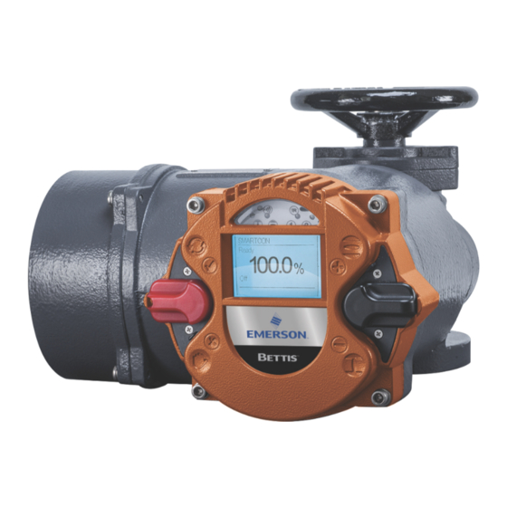
Emerson Bettis RTS Installation, Operation And Maintenance Manual
Extension board for modbus rtu
Hide thumbs
Also See for Bettis RTS:
- Installation, operation and maintenance manual (26 pages) ,
- Service manual (18 pages) ,
- Installation, operation and maintenance manual (18 pages)
Summary of Contents for Emerson Bettis RTS
- Page 1 Installation, Operation and Maintenance Manual VCIOM-16741-EN Rev. 0 November 2021 Bettis RTS Extension Board for Modbus RTU...
- Page 2 Notes Installation, Operation and Maintenance Manual November 2021 VCIOM-16741-EN Rev. 0 This page intentionally left blank...
-
Page 3: Table Of Contents
Installation, Operation and Maintenance Manual Table of Contents VCIOM-16741-EN Rev. 0 November 2021 Table of Contents Section 1: Extension Board for Modbus RTU on RTS Control Unit General Information ..................1 1.1.1 Communication Settings ..............1 Section 2: Connection Standard Design .................... 2 2.1.1 Connection Board (Customer End) ............. - Page 4 Notes Installation, Operation and Maintenance Manual November 2021 VCIOM-16741-EN Rev. 0 This page intentionally left blank...
-
Page 5: Section 1: Extension Board For Modbus Rtu On Rts Control Unit
RTS Control Unit General Information For Bettis RTS actuators, the standardized fieldbus interface Modbus RTU is available. This interface is a product option represented in hardware on the device, thus making it beneficial to advertise intended use upon ordering. Although, enabling Modbus RTU a posterior is possible, such upgrades should only be performed by authorized Emerson engineers or specially trained personnel. -
Page 6: Section 2: Connection
Section 2: Connection Installation, Operation and Maintenance Manual November 2021 VCIOM-16741-EN Rev. 0 Section 2: Connection Depedning on the order, here are the following connections possible: • standard design: connection board • explosionproof design: terminals Standard Design Connecting the actuator to the fieldbus system is accomplished through connecting the bus cable to the connection print in the connection compartment of the actuator. -
Page 7: Connecting To Modbus Rtu
Installation, Operation and Maintenance Manual Section 2: Connection VCIOM-16741-EN Rev. 0 November 2021 2.1.2 Connecting to Modbus RTU Recommended Cable Confectioning Prior to connection the bus lines are to be confectioned as seen in the Figure 2 below: Figure 2 The clamps on the connection board are designed for a maximum line cross-section of 1.5 mm . -
Page 8: Explosionproof Design
Section 2: Connection Installation, Operation and Maintenance Manual November 2021 VCIOM-16741-EN Rev. 0 Connecting at the End of a Strand, Bus Termination There is either no device connected to the bus in front or behind of the new Slave-Device. Line configuration: Figure 4 A. -
Page 9: Design With Binary Inputs And Outputs
Installation, Operation and Maintenance Manual Section 2: Connection VCIOM-16741-EN Rev. 0 November 2021 2.2.1 Design with Binary Inputs and Outputs Figure 5 Shielding connection clamp Additional frame Metallic cable glands (closed with blind screw connections at delivery) 4xM20x1.5 Terminal strip 2.2.2 Design without Binary Inputs and Outputs Figure 6... -
Page 10: Section 3: Setup
Section 3: Setup Installation, Operation and Maintenance Manual November 2021 VCIOM-16741-EN Rev. 0 Section 3: Setup If Modbus RTU is activated, the following additional parameters will be visible in the control menu of your Bettis Electric Actuator. Each device connected to a Modbus RTU-network has to receive a unique address during setup. -
Page 11: Section 4: Specification Of Input And Output Data
Section 4: Input and Output Data Installation, Operation and Maintenance Manual VCIOM-16741-EN Rev. 0 November 2021 Section 4: Specification of Input and Output Data General requirement: Depending on the Master it is possible that the Lowbyte (Bit 0 - 7) and the High byte (Bit 8 - 15) are to be switched. -
Page 12: Command
Section 4: Input and Output Data Installation, Operation and Maintenance Manual November 2021 VCIOM-16741-EN Rev. 0 4.1.2 Command Register number: 2, address 0001 Data format: 16 bit (Bitfield) Table 4. Description Bit no. Function Bit = 0 Bit = 1 OPEN OPEN in REMOTE mode. -
Page 13: Command 2
Section 4: Input and Output Data Installation, Operation and Maintenance Manual VCIOM-16741-EN Rev. 0 November 2021 4.1.3 Command 2 Register number: 3, address 0002 Data format: 16 bit (Bitfield) Table 5. Description Bit no. Function Bit = 0 Bit = 1 Bus Bit 1 Bus Bit 2 Bus Bit 3... -
Page 14: Output Data Modules (Slave To Master Communication)
Section 4: Input and Output Data Installation, Operation and Maintenance Manual November 2021 VCIOM-16741-EN Rev. 0 Output Data Modules (Slave to Master Communication) Output data can be handled with following Modbus functions: Table 6. Function 03 (03 hex) Read Holding Register Reads one single register from the slave. -
Page 15: Status
Section 4: Input and Output Data Installation, Operation and Maintenance Manual VCIOM-16741-EN Rev. 0 November 2021 4.2.2 Status Register number: 258, address 0101 Data format: 16 bit (Bitfield) Table 8. Description Bit no. Function Bit = 0 Bit = 1 READY Actuator is ready. -
Page 16: Actual Speed Value
Section 4: Input and Output Data Installation, Operation and Maintenance Manual November 2021 VCIOM-16741-EN Rev. 0 4.2.4 Actual Speed Value Register number: 260, address 0103 Data format: 16 bit, only the lowest 8 bit (Bit 7: Direction OPEN; Bit 6 - 0 : 0 - 100 corresponding to 0 - 100%) are in use. -
Page 17: Status 3
Section 4: Input and Output Data Installation, Operation and Maintenance Manual VCIOM-16741-EN Rev. 0 November 2021 4.2.7 Status 3 Register number: 263, address 0106 Data format: 16 bit, error codes Table 10. Error Code Corresponds Motor temperature warning. Motor temperature power-off. Phase order error or phase failure. - Page 18 P. R. China Székesfehérvár 8000 T +86 22 8212 3300 Hungary The Emerson logo is a trademark and service mark of Emerson Electric Co. T +36 22 53 09 50 Bettis is a mark of one of the Emerson family of companies.


Need help?
Do you have a question about the Bettis RTS and is the answer not in the manual?
Questions and answers