Table of Contents
Advertisement
Quick Links
Instruction Manual
D104435X012
November 2021
ODORANT INJECTION SYSTEM
SUMMARY:
Introduction ....................................................................... 2
Product Description .......................................................... 2
Characteristics .................................................................. 4
Control Panel .................................................................. 10
ATEX Requirements ........................................................11
Transport and Handling ...................................................11
Storage ............................................................................11
Installation .......................................................................11
Components Positioning..................................................11
Components Connections .............................................. 17
Startup ............................................................................ 20
Operation ........................................................................ 22
Touch Screen Panel ....................................................... 23
How to Do the Authentication ......................................... 24
How to Enter a Numeric Value ....................................... 24
Access Levels HMI ......................................................... 25
Process Data: Injection................................................... 26
Process Data: Injection................................................... 27
Process Data: Absorption ............................................... 27
Active Alarms .................................................................. 28
Alarm History .................................................................. 28
Alarm Thresholds ........................................................... 29
Alarms Description ......................................................... 31
Warning Description ....................................................... 34
Configuration Backup ..................................................... 35
Configuration .................................................................. 36
Date/Time ....................................................................... 36
Language........................................................................ 37
Serial Port ...................................................................... 37
User ............................................................................... 38
Tank ............................................................................... 40
Injection Panel ................................................................ 42
Manual ........................................................................... 45
Cleaning ......................................................................... 46
Input/Output ................................................................... 47
Web Server ..................................................................... 49
Log File e Configuration File........................................... 53
FTP Access .................................................................... 54
Modbus Table ................................................................. 55
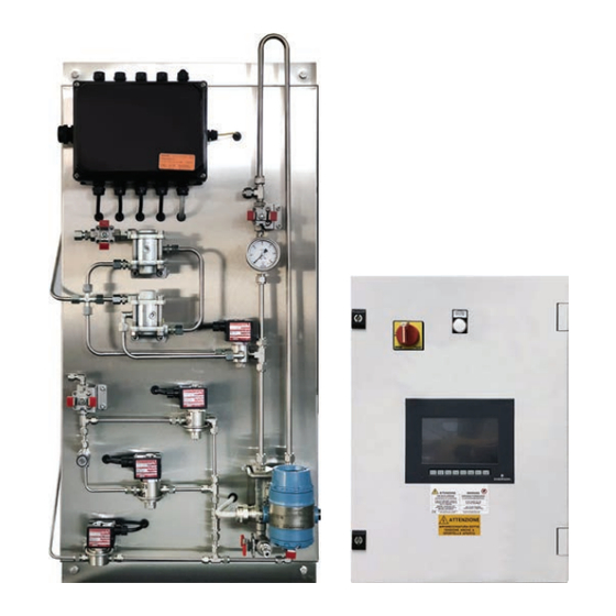
Dosaodor DO200
Figure 1. Dosaodor DO200 Injection Panel and Control Panel
WARNING
!
Only qualified and instructed personnel can
install and handle the odorant tank.
The odorizing system must be installed,
operated and maintained in accordance to all
applicable rules and standards.
Follow the instructions, especially the ones
relevant to "pressure risk".
The installation, operation and maintenance
procedures, if not performed by qualified
personnel, can be dangerous.
These circumstances can lead to damage
to the devices, injuries to people or damage
to properties due to gas or liquid leakage.
If there is a leak in the system, the released
gas can accumulate and provoke fires
or explosions.
Advertisement
Table of Contents

Subscribe to Our Youtube Channel
Related Manuals for Emerson Dosaodor DO200


Summary of Contents for Emerson Dosaodor DO200
-
Page 1: Table Of Contents
How to Do the Authentication ......... 24 How to Enter a Numeric Value ........24 Access Levels HMI ............25 Process Data: Injection........... 26 Figure 1. Dosaodor DO200 Injection Panel and Control Panel Process Data: Injection........... 27 Process Data: Absorption ..........27 Active Alarms ..............28 Alarm History .............. -
Page 2: Introduction
The Dosaodor DO200 is a Smart odorant system for natural gas, that injects odorant proportional to the flow rate of The same differential pressure transmitter measures in the gas in transit. - Page 3 Injection + Absorption type; in this case the backup is ensured by the second Dosaodor DO200. The regulation of the gas flow is performed through the needle valve installed on the tank.
-
Page 4: Characteristics
Dosaodor DO200 CHARACTERISTICS Control Panel Cabinet material / Protection degree Resin / IP55 Installation Wall Power Requirements 24 Vdc 100-240 Vac 50/60 Hz Consumption 120 W @ 24 Vdc Electromagnetic interferences Compliant to 89/336/CE Operating temperature 0 +40 °C Humidity... - Page 5 30 kg Sampling cylinder characteristics (optional) Refer to Emerson offices for proper application. The sampling cylinder tank will be delivered already installed in the Dosaodor DO200 injection panel. The injection panel has been designed to hold sampling cylinder tank weight.
-
Page 6: Injection Panel With Single Injector With Sampling Tube
Dosaodor DO200 INJECTION PANEL WITH SINGLE INJECTOR WITH SAMPLING TUBE Key Description Sampling tube Multipolar cable inlet dPT Pressure differential level transmitter EV1 Loading solenoid valve EV3 Dosing solenoid valve EV4 Pressurization solenoid valve Pressure gauge Pressure reducer I° stage Pressure reducer II°... -
Page 7: Injection Panel With Single Injector With Sampling Cylinder
Dosaodor DO200 INJECTION PANEL WITH SINGLE INJECTOR WITH SAMPLING CYLINDER Key Description Sampling cylinder Multipolar cable inlet dPT Pressure differential level transmitter EV1 Loading solenoid valve EV3 Dosing solenoid valve EV4 Pressurization solenoid valve Pressure gauge Pressure reducer I° stage Pressure reducer II°... -
Page 8: Injection Panel With Double Injector With Sampling Tube
Dosaodor DO200 INJECTION PANEL WITH DOUBLE INJECTOR WITH SAMPLING TUBE Key Description Sampling tube Multipolar cable inlet dPT Pressure differential level transmitter EV1 Loading solenoid valve EV2 Low dosing solenoid valve EV3 High dosing solenoid valve EV4 Pressurization solenoid valve Pressure gauge Pressure reducer I°... -
Page 9: Injection Panel With Double Injector With Sampling Cylinder
Dosaodor DO200 INJECTION PANEL WITH DOUBLE INJECTOR WITH SAMPLING CYLINDER Key Description Sampling cylinder Multipolar cable inlet dPT Pressure differential level transmitter EV1 Loading solenoid valve EV2 Low dosing solenoid valve EV3 High dosing solenoid valve EV4 Pressurization solenoid valve Pressure gauge Pressure reducer I°... -
Page 10: Control Panel
Dosaodor DO200 CONTROL PANEL ELECTRICAL POWER PANEL DOOR LOCK SUPPLY LAMP MAIN SWITCH PANEL DOOR LOCK INTERFACE RELAYS SWITCH ETHERNET POWER SUPPLY FUSES MAIN SWITCH POWER SUPPLY TERMINAL UNIT SOLENOID VALVES FUSES Figure 6. Control panel Main Parts... -
Page 11: Atex Requirements
(ref.: EN 12186). and electric isolation to avoid any corrosion. Dosaodor DO200 is sold on the market with all its complementary parts, like for example the bypass for • Gas must be cleaned through dedicated activating the absorption type system, the material for... - Page 12 Dosaodor DO200 Figure 7. Connections Schematic of Dosaodor DO200 System with Absorption and Inlet Pressure Supply...
- Page 13 Dosaodor DO200 Figure 8. Connections Schematic of Dosaodor DO200 System with Absorption and Cylinders Pack Supply...
- Page 14 Dosaodor DO200 Figure 9. Connections Schematic of Dosaodor DO200 Master / Slave System with Absorption and Inlet Pressure Supply...
- Page 15 Dosaodor DO200 Figure 10. Connections Schematic of Dosaodor DO200 Master / Slave System with Absorption and Cylinders Pack Supply...
- Page 16 Dosaodor DO200 Injection Pressures Greater than 6 bar Vent to safe area Qty Description PRX/181 Tap NAM 1/2” M-F RX/181 pilot – FKM – setting = 6 bar Relief valve – FKM – 1/4” NPT-M setting = 7 bar Solenoid valve 3-way DN 1/4” NPT-F, Eexd Straight fitting DN 1/4”...
-
Page 17: Components Connections
JUNCTION DEVICES BOX S supporting wall. The Dosaodor DO200 system includes an accessory kit Brown necessary for the standard installation of the system. For the Blue installation of the optional absorption type system refer to LOAD Figure 6. - Page 18 Dosaodor DO200 Table 3. Electrical Connection of the Differential Level Pressure Transmitter to the Junction Box JUNCTION DEVICES BOX S PWR + DP LEVEL TRANSMITTER COMM - Ground SIGNAL + CYLINDERS SIGNAL - PRESSURE Ground SIGNAL + TANK LEVEL TRANSMITTER...
- Page 19 Dosaodor DO200 Electric Connections in the Control panel Figure 15. Control Panel Electrical Terminal Table 5. Electrical Connection of the Junction Box to the Control Panel DESCRIPTION TERMINAL UNIT TYPE Control Panel Power Supply Power supply 230 Vac 24 V...
-
Page 20: Startup
If the startup is correct, the display located on the control to startup. panel will switch on and show in sequence the splash screen with Emerson logo, and then the home page = “OVERVIEW”. Equipment operating at high pressure should be warmed up slowly and uniformly before applying full pressure. - Page 21 Dosaodor DO200 System startup The Dosaodor DO200 has two work phases that are The system is delivered pre-configured in the factory with performed in a cyclic sequence: LOAD phase and the parameters necessary for its operation based on the INJECTION phase.
-
Page 22: Operation
Ordinary /Extraordinary Maintenance that handle flammable and/or odorant liquids. Operations It is evident that Emerson’s Dosaodor DO200 dosing system, based on its technology materials and equipment used, including field experiences, generally requires routine maintenance once every three solar years. -
Page 23: Touch Screen Panel
Dosaodor DO200 TOUCH SCREEN PANEL Panoramic - Injection + Absorption Visible if present Visible if present Menu Overview: if pressed, you pass to the mail screen. Menu Process Data: if pressed, you pass to the page of data process index. -
Page 24: How To Do The Authentication
Dosaodor DO200 HOW TO DO THE AUTHENTICATION Pressing Login at the bottom, on the left, the following screen opens: Name: tapping this field opens an alphanumeric keyboard and you can enter the username Password: tapping this field opens an alphanumeric keyboard and you can enter the password... -
Page 25: Access Levels Hmi
Dosaodor DO200 ACCESS LEVELS HMI Table 7. HMI Level GROUP IN HMI PASSWORD USER 1:SecurityGroup01 Viewer aaaa 2:SecurityGroup02 bbbb 3:SecurityGroup03 Admin cccc 1 is the lowest access, 3 the highest: Viewer • The main system parameters are only visible (Overview, Process Data, Alarms pages) •... -
Page 26: Process Data: Injection
Dosaodor DO200 PROCESS DATA: INJECTION Process Data\Injection page. Process Data\Cycle page. Process Data\Absorption page. Numeric visualization of odorant g injected in the current hour. Numeric visualization of odorant g injected in the current day. Numeric visualization of odorant g injected in the current month. -
Page 27: Process Data: Injection
Dosaodor DO200 PROCESS DATA: CYCLE Numeric visualization of odorant g injected in the previous cycle. Numeric visualization of CH4 mc passed in the previous cycle. Numeric visualization of concentration calculated in the previous cycle. Number of odorant pulses calculated in the previous cycle. -
Page 28: Active Alarms
Dosaodor DO200 ACTIVE ALARMS In this page are displayed the currently active alarms. Column date of the alarm: displays the date when the alarm was triggered. Column time of the alarm: displays the time when the alarm was triggered. Number id of the alarm. -
Page 29: Alarm Thresholds
Dosaodor DO200 ALARM THRESHOLDS With level access operator: Button On/Off STEADY GAS FLOWRATE This key activates (or deactivates) the “steady gas flowrate” function. If it’s green (ON), in case of gas flowrate sensor failure, the system simulates the flow value with the value set in the field 2; if red (OFF), in case of gas flowrate sensor failure, the system does not simulate the flow value. - Page 30 Dosaodor DO200 10. Field SET NUMBER OF CYCLES PER BLOCK If pressed, it allows to set the number of consecutive cycles with a ratio calculated outside the established precision band (ODORANT CONCENTRATION ALARM). 11. Display SET NUMBER OF CYCLES PER BLOCK Display of the count of cycles performed with an inaccurate value.
-
Page 31: Alarms Description
Dosaodor DO200 ALARMS DESCRIPTION Table 8. Alarms ALARM NAME WHEN ACTIVATED WHAT DOES IT DO HOW TO REARM WHAT TO CHECK It is activated when the system is Monitor Signaling, disable excluded, i.e. injection is disabled Alarm system in manual mode... - Page 32 Dosaodor DO200 Table 8. Alarms (continue) ALARM NAME WHEN ACTIVATED WHAT DOES IT DO HOW TO REARM WHAT TO CHECK Is activated when the level of the Alarm threshold low SPARE 1 / SPARE 1 / Cylinders pressure Monitor Signaling,...
- Page 33 Dosaodor DO200 ALARM NAME WHEN ACTIVATED WHAT DOES IT DO HOW TO REARM WHAT TO CHECK If connected to a battery charger, Activates to signal that the check / monitor its correct operation batteries are below a certain Alarm low battery autonomy...
-
Page 34: Warning Description
Dosaodor DO200 WARNINGS DESCRIPTION Table 9. Warning WARNING WHEN ACTIVATED WHAT DOES IT DO HOW TO REARM ALARM RESET DESCRIPTION Signaling to monitors only if the redundant solenoid valves Activates when incorrect exchange is controlled and operation occurs during the... -
Page 35: Configuration Backup
Dosaodor DO200 CONFIGURATION BACKUP The fourth section of the left menu, visible and accessible only at the administrator level, is about saving (downloading) and uploading the configuration of system parameters to and from the memory of the PLC, respectively. Configuration name (not editable) Button SAVE DO200 Pressing this key, the program upload the configuration data saved in a .rcp extension file in the PLC memory, loading it into... -
Page 36: Configuration
Dosaodor DO200 CONFIGURATION HMI Setup The fifth section, visible and available only under administrator access, is regarded to the following HMI setup: Date/Time: if pressed, you pass to the timestamp synchronization screen. Language: if pressed, you pass to the language selection for the HMI’s pages. -
Page 37: Language
Dosaodor DO200 LANGUAGE On this screen you can select the language for the HMI’s pages. SERIAL PORT On this screen, you can set the configuration parameters of the serial port 1. Once the data has been entered, the button 1 (Save) -
Page 38: User
Dosaodor DO200 USER This section is dedicated to the user management and to the related password to access the system. In this screen it is possible to add, delete and edit the user name and its password from the default (not editable) structured HMI levels, visible by clicking on the group pane of the currently logged-on user (Group), which is allowed and limited to all levels below the maximum (Administrator). - Page 39 Dosaodor DO200 How to Change Password of an Existing Users Open the Group field drop-down menu by pressing the button . From the list that appears, select the membership group of the user for whom you want to change the password.
-
Page 40: Tank
Dosaodor DO200 TANK The TANK page summarizes the settings on the data of the same, both. Display of the maximum capacity of the tank. Charge Time (Cycle) This parameter indicates the waiting time from the moment in which the liquid level inside the sample tube during the loading phase is stable;... - Page 41 Dosaodor DO200 Geometric Configuration of the Tank Offset Transmitter-Tank: is the delta level (in mm) between the zero point level of the DP transmitter and the zero point level of the tank. Zero Level Reference Max capacity: is maximum capacity of the tank (l).
-
Page 42: Injection Panel
Dosaodor DO200 INJECTION PANEL Configuration Estimated End Cycle Time is the estimate duration of the cycle (min). Set gas vol. cycle is the volume of gas that can be odorized with the quantity of liquid loaded, in relation to the concentration set. - Page 43 Dosaodor DO200 WARNING The modification of the parameters and the operations described in the following paragraphs must be carried out by expert technicians. Incorrect operations and / or incorrect parameters can seriously compromise the operation of the Dosaodor DO200. Visible if the injection...
- Page 44 Dosaodor DO200 Dosage Injection control time. It is the update time for the injection control. Injection minimum opening time. It is the injection solenoid valve minimum opening time. Injection maximum opening time. It is the injection solenoid valve maximum opening time.
-
Page 45: Manual
Dosaodor DO200 MANUAL ACTIONS Tank Level in millimeters (mm) and tank volume in liters (l). Sampling tube level in millimeters (mm). Liquid Charge. That button drives the charging solenoid valve. The action is retentive. • RED = Not active = Closed •... -
Page 46: Cleaning
Dosaodor DO200 CLEANING The basic operations for emptying the liquid in the injection panel are described below. WARNING The operations described in the following paragraphs must be carried out by expert technicians. Incorrect operations can seriously dangerous. Moving liquid procedure from the injection panel to the tank Click on Pressurization Solenoid (6) to put added pressure on the injection panel. -
Page 47: Input/Output
Dosaodor DO200 INPUT/OUTPUT PULSE FLOW RATE This section is dedicated to the impulsive volumetric flow rate signal. By pressing the button ON/OFF is possible to activate or deactivate the function and enter the weight for each impulse received. • RED = Not active = OFF •... - Page 48 Dosaodor DO200 SPARE 1 Here it is possible to set the parameters relating to the SPARE 1 analog input: the zero, the span and the offset of the analog input (4-20mA), the description, the engineering unit and monitor the instantaneous electrical value acquired. By Pressing the button ON/OFF is possible to activate ore deactivate the SPARE 1 analog input.
-
Page 49: Web Server
Dosaodor DO200 WEB SERVER Within the Dosaodor DO200 are residents 2 different web servers. HMI Web Server The HMI web server allows remote viewing on the WEB page of the graphic pages contained within the HMI Operator Panel by connecting to the local LAN of the DO200 control panel, or by remote connection Via browser (MS Internet Explorer) by entering the HMI IP address in the address bar, the following screen will be displayed: The default IP address is http://10.0.0.3/, if this has been changed, enter the new IP address in the address bar. - Page 50 If the view is locked, you must proceed with the Plug-In installation (Schneider Electric) following the following instructions: • Install the Web_Gate_Client_Files_6.2_sp8.exe and enter the address If you do not have the right Web_Gate_Client request it to your Emerson’s referents. • Insert the HMI IP into trusted sites Click Tools >...
- Page 51 Dosaodor DO200 • After you complete these steps restart your browser and reopen the web server by clicking Monitoring > Web Gate > In Frame. In case of further failure with this access mode, an alternative is to use the Chrome browser following these steps: •...
- Page 52 Dosaodor DO200 PLC Web Server The web server PLC has a lower graphical representation and limited functionality, compared to the HMI web server. It is recommended to be used in those situations where company security policies do not allow the installation of graphical plug-in software for Internet Browsers.
-
Page 53: Log File E Configuration File
Dosaodor DO200 LOG FILE E CONFIGURATION FILE Data Log The system records, on a file (*.log) in the SD memory of the PLC, the operating data with a sampling every 5 minutes organized by months for a maximum of 1 year of operation. Access path: ftp://10.0.0.2/sd0. -
Page 54: Ftp Access
Dosaodor DO200 Configuration File he system allows to save the configuration to a file (*.rcp) in the PLC’s Flash memory. Access path: ftp://10.0.0.2/usr/Rcp. The configuration files are editable and therefore it is suggested to copy them to a local folder if you want to change them (making sure to change only the values in the case of the configuration parameter list) and then drag them to the source ftp path for upload. -
Page 55: Modbus Table
Dosaodor DO200 MODBUS TABLE All registers are to be considered 4x Output Register. To be able to read the data, apply a word Swapping starting from the decimal address. Table 12. Modbus ADDRESS (4x holding registers) VARIABLE DESCRIPTION READ/WRITE DATA TYPE... - Page 56 Dosaodor DO200 Table 12. Modbus (continue) ADDRESS (4x holding registers) VARIABLE DESCRIPTION READ/WRITE DATA TYPE Decimal 056: Alarm sampling tube internal diameter equal to ZERO BOOL 057: Alarm cylinder (tank) external diameter equal to ZERO BOOL 058: Alarm cylinder wall thickness equal to ZERO...
- Page 57 Dosaodor DO200 ADDRESS (4x holding registers) VARIABLE DESCRIPTION READ/WRITE DATA TYPE Decimal Reset of Absorption system totalizers BOOL Saves the configuration parameters in the PLC memory BOOL Upload of the list of configuration parameters from the memory BOOL Save serial port configuration parameters 1...
- Page 58 Dosaodor DO200 Table 12. Modbus (continue) ADDRESS (4x holding registers) VARIABLE DESCRIPTION READ/WRITE DATA TYPE Decimal Serial Port 2 - RS485 (0: RS232; 1: RS485) Serial Port 2 - Codesys Compliant (0: Modbus RTU; 1: SoMachine (when Protocol = 0)) Serial Port 2 - Dataformat (7 bits or 8 bits) Serial Port 2 - Modbus (0: Modbus RTU o SoMachine (see Codesys Compliant);...
- Page 59 Dosaodor DO200 ADDRESS (4x holding registers) VARIABLE DESCRIPTION READ/WRITE DATA TYPE Decimal Maximum injection time (ms) REAL Injection pulse time (ms) REAL K Proportional REAL K Integrative REAL Sample Tube internal diameter (mm) REAL Minimum level transmitter reading height (mm)
- Page 60 Responsibility for proper selection, use and maintenance of any C.F. - P.I. e R.I. di MI 13186130152 - REA di MI/n.1622916 Emerson Process Management Regulator Technologies, Inc. product Direz. e Coord. (art. 2497 bis CC): EMERSON ELECTRIC CO. St. Louis (USA) Socio Unico remains solely with the purchaser.
Need help?
Do you have a question about the Dosaodor DO200 and is the answer not in the manual?
Questions and answers