
Subscribe to Our Youtube Channel
Related Manuals for Lanner LEC-2290E


Summary of Contents for Lanner LEC-2290E
- Page 1 LEC-2290E User Manual Embedded Computing Platform LEC-2290E User Manual Version: 1.0 Date of Release: 2021-11-16...
- Page 2 LEC-2290E User Manual The icons are used in the manual to serve as an indication of interest topics or important messages. Below is a description of these icons: Note: This mark indicates that there is a note of interest and is something that you should pay special attention to while using the product.
- Page 3 LEC-2290E User Manual Taiwan Corporate Headquarters China Lanner Electronics Inc. Beijing L&S Lancom Platform Tech. Co., Ltd. 7F, No.173, Sec.2, Datong Rd. Guodong LOFT 9 Layer No. 9 Huinan Road, Xizhi District, New Taipei City 22184, Huilongguan Town, Changping District, Beijing...
- Page 4 LEC-2290E User Manual Intel® and Intel® Atom® are trademarks of Intel Corporation or its subsidiaries in the U.S. and/or other countries. Microsoft Windows and MS-DOS are registered trademarks of Microsoft Corp. All other product names or trademarks are properties of their respective owners.
- Page 5 LEC-2290E User Manual Follow these guidelines to ensure general safety: Keep the chassis area clear and dust-free during and after installation. Do not wear loose clothing or jewelry that could get caught in the chassis. Fasten your tie or scarf and roll up your sleeves.
- Page 6 The installation of this product must be performed by trained specialists; otherwise, a non-specialist might create the risk of the system’s falling to the ground or other damages. Lanner Electronics Inc. shall not be held liable for any losses resulting from insufficient strength for supporting the system or use of inappropriate installation components.
- Page 7 LEC-2290E User Manual Before turning on the device, ground the grounding cable of the equipment. Proper grounding (grounding) is very important to protect the equipment against the harmful effects of external noise and to reduce the risk of electrocution in the event of a lightning strike.
- Page 8 LEC-2290E User Manual Package Content..........................9 Ordering Information ......................... 9 Optional Accessories .......................... 9 System Specifications ........................10 Motherboard Information........................ 14 Internal Jumpers and Connector ...................... 17 Open the Chassis ..........................32 Installing the Disk Drive ........................33 Installing 4G Module ........................34 Installing Memory Card ........................
- Page 9 (codenamed Coffee Lake) and features up to 32GB DDR4 memory, 4x PoE for camera connections and PCIe/Mini-PCIe slots for GPU cards. LEC-2290E comes with support of Intel® Distribution of OpenVINO™ Toolkit and Movidius inferencing engine to realize high-performance intelligent edge computing applications like compute-intensive video analytics.
- Page 10 LEC-2290E User Manual Intel® Core™ i7-8700 (Codenamed Coffee Lake) 3.2 GHz Frequency Processor System 6 cores Core Number C246 Chipset Fanless DDR4 2133/2400 SO-DIMM Technology Up to 32 GB Memory Max. Capacity 2x 260-pin SO-DIMM Socket Intel® UHD Graphics 630...
- Page 11 LEC-2290E User Manual 0° C~40° C Operating Temperature -40° C~70° C Storage Temperature Environment 10%~90% Non-condensing Relative Humidity IEC 60068-2-64, 0.5Grms, random 5~500Hz, 40 mins/axis Vibration 275 x115 x 225mm Dimension (W x H x D) 6.2 kg Mechanical Weight...
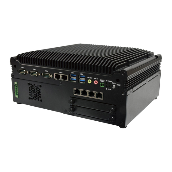
- Page 12 LEC-2290E User Manual PoE2 PoE3 PoE4 PoE1 HDD1 HDD2 Description COM Port 3x DB9 Male Connector for RS232/422/485 GbE Port 2x RJ45 port with LED indicators USB 3.0 Port 4x USB 3.0 Type A Audio Jack 3.5mm Line-out and Line-in Jack...
- Page 13 LEC-2290E User Manual Description 1x 20 pin terminal block 8 DI (12V) & 8 DO (12V,100mA) Isolation Display Port 1x Display Port HDMI Port 2x HDMI Port COM Port 3x DB9 Male Connector for RS232/422/485 1x 4-pin terminal block for DC 9~36V system power source...
- Page 14 LEC-2290E User Manual The block diagram indicates how data flows among components on the motherboard. Please refer to the following figure for your motherboard’s layout design.
- Page 15 LEC-2290E User Manual DDR4 DDR4 JNGFF1 Expansion Storage MSATA1 MPCIE1...
- Page 16 LEC-2290E User Manual IPMI Card PCIe...
- Page 17 LEC-2290E User Manual DESCRIPTION DESCRIPTION WAKE# +3.3V RSVD RSVD +1.5V CLKREQ# UIM_PWR UIM_DATA REFCLK- UIM_CLK REFCLK+ UIM_RESET UIM_VPP KEY B RSVD RSVD W_DISABLE# PERST# PERn0 +3.3V PERp0 +1.5V SMB_CLK PETn0 SMB_DATA PETp0 USB_D+ MPCIE USB_D- +3.3V +3.3V LED_WWAN# LED_WLAN# RSVD...
- Page 18 LEC-2290E User Manual CONFIG0 AUDIO_0 AUDIO_1 AUDIO_2 AUDIO_3 PERn1/USB3RX- UIM_RFU PERp1/USB3RX+ UIM_RESET UIM_CLK PETn1/USB3TX- UIM_DATA PETp1/USB3TX+ UIM_PWR DEVSLP PETn0/SATA_B+ GNSS0 PETp0/SATA_B- GNSS1 GNSS2 PERn0/SATA_A- GNSS3 PERp0/SATA_A+ GNSS4 PRESET# REFCLK- CLKREQ# REFCLK+ WALE# ANTCTL0 ANTCTL1 COEX3 ANTCTL2 COEX2 ANTCTL3 COEX1 PEDET...
- Page 19 LEC-2290E User Manual HSOP0 REFCLKA- HSON0 HSIP0 PRSNT2# HSIN0 HSOP1 RSVD HSON1 HSIP1 HSIN1 HSOP2 HSON2 HSIP2 HSIN2 HSOP3 HSON3 HSIP3 RSVD HSIN3 PRSNT2# RSVD(REFCLKB+) HSOP4 RSVD(REFCLKB-) HSON4 HSIP4 HSIN4 HSOP5 HSON5 HSIP5 HSIN5 HSOP6 HSON6 HSIP6 HSIN6 HSOP7 HSON7...
- Page 20 LEC-2290E User Manual HSON8 HSIP8 HSIN8 HSOP9 HSON9 HSIP9 HSIN9 HSOP10 HSON10 HSIP10 HSIN10 HSOP11 HSON11 HSIP11 HSIN11 HSOP12 HSON12 HSIP12 HSIN12 HSOP13 HSON13 HSIP13 HSIN13 HSOP14 HSON14 HSIP14 HSIN14 HSOP15 HSON15 HSIP15 PRSNT2# HSIN15 RSVD(CARD_DET#)
- Page 21 LEC-2290E User Manual DESCRIPTION DESCRIPTION PRSNT1# SMCLK JTAG2 SMDAT JTAG3 JTAG4 3.3V JTAG5 JTAG1 3.3V 3.3VAUX 3.3V WAKE# PERST# KEY B RSVD REFCLK+ HSOP0 REFCLK- HSON0 HSIP0 PRSNT2# HSIN0 HSOP1 PoE_INT HSON1 HSIP1 HSIN1 HSOP2 HSON2 HSIP2 HSIN2 HSOP3 HSON3...
- Page 22 LEC-2290E User Manual USB3_TX5+ USB3_TX5- USB3_RX5+ USB3_RX5- SATA_TX1+ SATA_TX1- SATA_RX1+ SATA_RX1- SATA_TX2+ SATA_TX2- SATA_RX2+ 4G_PERST# SATA_RX2- VSIM_SW DESCRIPTION DESCRIPTION Card detect P12V_ADC11 / GPIX3 GND1 RSVD9 I2C_SCL8 / GPIOK6 SYS_UART2_DCD I2C_SDA8 / GPIOK7 SYS_UART2_DSR RSVD1 SYS_UART2_CTS RSVD2 SYS_UART2_RI TACH4 / GPIOO4...
- Page 23 LEC-2290E User Manual SYS_UART1_CTS SYS_UART1_RI GND5 SYS_UART1_DTR PWM5 / GPION5 SYS_UART1_RTS PWM3 / GPION3 GND35 PWM0 / GPION0 RSVD12 PWM1 / GPION1 CPU_CORE1_ADC1 / GPIW1 GND6 ADC5 / GPIW5 TACH1 / GPIOO1 ADC4 / GPIW4 TACH0 / GPIOO0 ADC7 / GPIW7...
- Page 24 LEC-2290E User Manual GND12 GND42 PERXP I2C_SCL2_MB_ID_EEPROM/LOM_EEPROM PERXN I2C_SDA2_MB_ID_EEPROM/LOM_EEPROM GND13 GND43 PETXP PERST# PETXN GND44 GND14 RSVD15 PEREFCLKP RSVD16 PEREFCLKN GND45 GND15 SOL_UART_DCD SOL_UART_DSR SOL_UART_RI SOL_UART_DTR SOL_UART_RTS GND16 GND46 SYSCS# / GPIOI0 SYS_UART_SWITCH_OUT SYSMISO / GPIOI3 BIOS_READY_IN SYSCK / GPIOI1...
- Page 25 LEC-2290E User Manual GND21 I2C_SCL3_SMLink0 CPU_ERR_0_IN GND51 CPU_ERR_1_IN I2C_SCL4_PMBus CPU_ERR_2_IN I2C_SDA4_PMBus GND31 GND52 USB2A_DP BMC_NMI_OUT USB2A_DN CPU1_PROCHOT_IN GND22 GND53 RSVD7 LAN_100M# RSVD8 LAN_ACT# GND23 LAN_1G# SOL_CTS3 GND54 SOL_TXD3 GPIOA1_MAC2LINK SOL_RXD3 RGMII2RXD3 / RMII2RXER / GPIOV7 GND24 RGMII2RXD0 / RMII2RXD0 / GPIOV4...
- Page 26 LEC-2290E User Manual DESCRIPTION DESCRIPTION +3.3V SATA_RXp +3.3V SATA_RXn MSATA SATA_TXn SATA_TXp +3.3V +3.3V +3.3V DESCRIPTION DESCRIPTION LANE0+ LANE0- LANE1+ LANE1- LANE2+ LANE2- LANE3+ LANE3- AUX CH+ AUX CH- HOT PLUG RETURN DP PWR...
- Page 27 LEC-2290E User Manual DESCRIPTION DESCRIPTION DATA2+ DATA2- DATA1+ DATA1- DATA0+ DATA0- CLK+ CLK- DDC CLK DDC DAT HDMI_VCC DESCRIPTION Fast E-Net Giga Net MD0+ MD0- MD1+ MD2+ MD2- MD1- MD3+ MD3- 10-/100-/1000+ 10+/100+/1000- Link+/ACT- Link-/ACT+ DESCRIPTION USB1_TX+ USB1_TX- USB1_RX+ USB1_RX-...
- Page 28 LEC-2290E User Manual DESCRIPTION USB1_TX+ USB1_TX- USB1_RX+ USB1_RX- DESCRIPTION USB_VCC1 USB1_D- USB1_D+ DESCRIPTION DESCRIPTION USB_VCC +USB -USB -USB +USB USB1 USB_VCC DESCRIPTION DESCRIPTION DESCRIPTION DCD# RxTx- RxTx+ DTR# RTS# CTS# DESCRIPTION DESCRIPTION DO_0 DI_0 DO_1 DI_1 DO_2 DI_2 DO_3 DI_3...
- Page 29 LEC-2290E User Manual DO_7 DI_7 DO_COM I_COM DO_COM 12V_OUT(400mA) DESCRIPTION DESCRIPTION LINE_OUT_L MIC_L LINE_OUT_R MIC_R DESCRIPTION DC_IN (-) DC_IN (+) DC_IN (+) DC_IN (-) DESCRIPTION DESCRIPTION SPI_HOLD SPI_CS# SPI_VCC SPI_MO SPI1 SPI_CLK SPI_MI DESCRIPTION DESCRIPTION SPI_HOLD SPI_CS# SPI_VCC SPI_MO LPC1...
- Page 30 LEC-2290E User Manual DESCRIPTION DESCRIPTION SERIRQ# +3.3V LAD0 +3.3V LAD1 LFRAME# JTPM1 LPC_CLK PLTRST# LAD2 LAD3 1 2 3 PIN NO. DESCRIPTION EXT_TX EXT_RX CMOS1 CMOS1 Description CMOS1 Normal(Def) Normal (Default) Clear CMOS Clear CMOS DESCRIPTION PS_IN DESCRIPTION DETECT POWER GOOD...
- Page 31 LEC-2290E User Manual Description Connect internal RS232(COM7) S1/S2 on S3/S4 off Connect external RS232 from CN1. /S2 off (Debug & update f.w) S3/S4 on Description. DESCRIPTION JIG1 Normal 1-2 Short IG mode 1-2 Open JIGBTN1 Description. DESCRIPTION Power button from MCU...
- Page 32 LEC-2290E User Manual To reduce the risk of personal injury, electric shock, or damage to the unit, please remove all power connections to completely shut down the device, and wear ESD protection gloves when conducting the steps in this chapter.
- Page 33 LEC-2290E User Manual The system supports two 2.5” HDD/SSD drive bays, with one 2.5” SSD drive included. The following will discuss disk drive installation procedures. 1. Power off the system and unplug the power cord. Unscrew the two thumbscrews that fix the tray on the system.
- Page 34 LEC-2290E User Manual This system comes with an external M.2 slot, supporting dual SIM design. The following will discuss the installation of 4G module and SIM cards. Loosen the two screws that secure the tray and draw out the tray by its grip.
- Page 35 LEC-2290E User Manual The system supports one (1) slot for mSATA memory card. Please follow the steps for installation. 1. Power off the system and open the system chassis cover. Locate the mSATA memory slot on the motherboard. 2. Align the notch of the memory card with the socket key in the pin slot.
- Page 36 LEC-2290E User Manual The motherboard supports two (2) memory slots for DDR4 registered DIMM. Please follow the steps for installation. 1. Power off the system and open the system chassis cover. Locate the memory slots on the motherboard. 2. Align the notch of the module with the socket key in the pin slot.
- Page 37 LEC-2290E User Manual LEC-2290E comes with a slot for GPU graphic card expansion. The GPU graphic card requires a rather complex installation process; therefore, the assembly must be handled with care. Please read through the instructions in this section to make sure you have acquired the necessary knowledge and comply with the requirements.
- Page 38 LEC-2290E User Manual 4. Open the top chassis. 5. First remove the secure casings parts (side part & bottom part). To remove the side part, unscrew the six (6) screws. Casing Side Part To remove the bottom part, unscrew the two (2) screws from the underside.
- Page 39 LEC-2290E User Manual 6. After removing the casing parts, install the swappable fans. Secure the fan with four (4) screws each. 7. Place the bottom casing part and secure with two (2) screws on the underside. 8. Install the GPU graphic card. Align...
- Page 40 LEC-2290E User Manual 10. Place the fan power cables through the side casing hole. 11. Gentle push the side casing part in place, and secure with six (6) screws. 12. Insert the fan power cables into the connectors.
- Page 41 LEC-2290E User Manual 13. Place the top chassis back and secure with four (4) screws. 14. Insert the bottom panel back, watch out for the PCIe pins and metal pillars. Secure with four (4) screws. 15. The GPU graphic card has been successfully installed.
- Page 42 LEC-2290E User Manual IPMI provides better server management, server monitoring, and remote access. IPMI is independent of the system’s CPU operating system via hardware applied directly into the motherboard. Please follow the steps for installation. 1. Power off the system and turn the system upside down.
- Page 43 LEC-2290E User Manual 4. Align the notch of the module with the socket key in the pin slot. 5. Insert the BMC card pins at 30 degrees into the socket until it is fully seated. Notch 6. Push down on the module until the slot latches catches and clicks into place.
- Page 44 LEC-2290E User Manual The system can be mounted on a flat surfaced wall. Please take the following into considerations when mounting the system onto the wall. 1. Fix the wallmount brackets onto the system bottom by securing them with four provided screws.
- Page 45 LEC-2290E User Manual On the wall, measure the exact place where you want to hang the system, and drill four holes that match the four mounting holes on both brackets. Insert four anchoring bolts into the holes. Align the four mounting holes on the system’s brackets with the four anchoring bolts you just installed on the wall.
- Page 46 LEC-2290E User Manual The system has AMI BIOS built-in, with a SETUP utility that allows users to configure required settings or to activate certain system features. Pressing the <Tab> or <Del> key immediately allows you to enter the Setup utility.
- Page 47 LEC-2290E User Manual Setup main page contains BIOS information and project version information. Feature Description BIOS Vendor: American Megatrends Core Version: AMI Kernel version, CRB code base, X64 Compliancy: UEFI version, PI version BIOS Information Project Version: BIOS release version...
- Page 48 LEC-2290E User Manual Select the Advanced menu item from the BIOS setup screen to enter the “Advanced” setup screen. Users can select any of the items in the left frame of the screen.
- Page 49 LEC-2290E User Manual...
- Page 50 LEC-2290E User Manual Feature Options Description Disabled Enable/Disable moving of DRAM contents to PRM C6DRAM Enabled memory when CPU is in C6 state Software Guard Disabled Enable/Disable Software Guard Extensions (SGX) Extensions (SGX) Enabled CPU Flex Ratio Disabled Enable/Disable CPU Flex Ratio Programming...
- Page 51 LEC-2290E User Manual Enabled for Windows XP and Linux (OS optimized for Disabled Hyper-Threading Technology) and Disabled for other Hyper-Threading Enabled optimized Hyper-Threading Technology). Disabled Enable/Disable BIST (Built-In Self Test) on reset BIST Enabled HALT Loop AP threads Idle Manner for waiting signal to run...
- Page 52 LEC-2290E User Manual Feature Options Description Max Battery Select the performance state that the BIOS will Boot performance Max Non-Turbo set starting from reset vector. mode Performance Turbo Performance" Intel(R) Disabled Allows more than two frequency ranges to be SpeedStep(tm) Enabled supported.
- Page 53 LEC-2290E User Manual Feature Options Description Disabled When Disabled ME will be put into ME Temporarily ME State Enabled Disabled Mode.
- Page 54 LEC-2290E User Manual Feature Options Description Disabled Enable/Disable Me FW Image Re-Flash function. Me FW Image Re-Flash Enabled...
- Page 55 LEC-2290E User Manual Feature Options Description Enables or disables BIOS support for security device. By Security Device Enabled disabling this function, OS will not show Security Support Disabled Device. TCG EFI protocol and INT1A interface will not be available.
- Page 56 LEC-2290E User Manual Feature Options Description Enables or disables BIOS support for security device. By Security Device Enabled disabling this function, OS will not show Security Support Disabled Device. TCG EFI protocol and INT1A interface will not be available. Enables or disables Security Device.
- Page 57 LEC-2290E User Manual...
- Page 58 LEC-2290E User Manual Feature Options Description Enables or disables BIOS support for security device. By Security Device Enabled disabling this function, OS will not show Security Support Disabled Device. TCG EFI protocol and INT1A interface will not be available. Enabled SHA-1 PCR Bank Enables or disables SHA-1 PCR Bank.
- Page 59 LEC-2290E User Manual...
- Page 60 LEC-2290E User Manual Feature Options Description Enabled Serial Port Enables or disables Serial Port 1. Disabled Device Settings IO=3F8h; IRQ = 4...
- Page 61 LEC-2290E User Manual Feature Options Description Enabled Serial Port Enables or disables Serial Port 2. Disabled Device Settings IO=2F8h; IRQ = 3...
- Page 62 LEC-2290E User Manual Feature Options Description Smart Fan Control None Smart Fan Parameters...
- Page 63 LEC-2290E User Manual Feature Options Description Manual Mode Smart Fan Mode Smart Fan Mode select Smart Fan Mode Target Input Target Temperature (Range:0 - 127) Temperature T1 Target Input Target Temperature (Range:0 - 127) Temperature T2 Target Input Target Temperature (Range:0 - 127)
- Page 64 LEC-2290E User Manual...
- Page 65 LEC-2290E User Manual Feature Options Description Watch Dog Timer Enabled Enables or disables Watch Dog Timer function Disabled...
- Page 66 LEC-2290 User Manual Feature Options Description COM0 Enabled Enables or disables Console Redirection Console Redirection Disabled...
- Page 67 LEC-2290 User Manual Feature Options Description VT100: ASCII char set VT100 VT100+:Extends VT100 to support color, function keys, etc. VT100+ Terminal Type VT-UTF8:Uses UTF8 encoding to map Unicode chars onto 1 or VT-UTF8 more bytes ANSI ANSI: Extended ASCII char set 9600 19200 Selects serial port transmission speed.
- Page 68 LEC-2290 User Manual None Flow Control Hardware Flow Control can prevent data loss from buffer overflow. RTS/CTS VT-UTF8 Combo Key Disabled Enables VT-UTF8 Combination Key Support for ANSI/VT100 Support Enabled terminals Disabled With this mode enabled, only text will be sent. This is to capture Recorder Mode Enabled Terminal data.
- Page 69 LEC-2290 User Manual Feature Options Description Redirection COM COM0 Select a COM port to display redirection of Legacy Port OS and Legacy OPROM Messages. 80x24 On Legacy OS, the Number of Rows and Columns Resolution 80x25 supported redirection. When Bootloader is selected, Legacy Console Redirection is disabled before booting to legacy Redirection After Always Enable...
- Page 70 LEC-2290 User Manual...
- Page 71 LEC-2290 User Manual Feature Options Description Disabled Re-enable Bus Master Attribute disabled during Pci BME DMA Mitigation Enabled enumeration for PCI Bridges after SMM Locked Globally Enables or Disables Hot-Plug support for the entire Disabled System. If System has Hot-Plug capable Slots and this Hot-Plug Support Enabled option set to Enabled, it provides a Setup screen for...
- Page 72 LEC-2290 User Manual...
- Page 73 LEC-2290 User Manual Feature Options Description Enables Legacy USB support. Enabled Auto option disables legacy support if no Legacy USB Support Disabled USB devices are connected; Auto Disabled option will keep USB devices available only for EFI applications. This is a workaround for OSes without XHCI Enabled XHCI Hand-off hand-off support.
- Page 74 LEC-2290 User Manual Feature Options Description Disabled Network Stack Enables or disables UEFI Network Stack Enabled...
- Page 75 LEC-2290 User Manual Feature Options Description Disabled CSM Support Enables or disables CSM Support Enabled Do Not Launch Controls the execution of UEFI and Legacy Network UEFI PXE OpROM Legacy Do Not Launch Controls the execution of UEFI and Legacy Storage UEFI Storage OpROM...
- Page 76 LEC-2290 User Manual...
- Page 77 LEC-2290 User Manual Feature Options Description Control Disabled Legacy PXE MGMT Lan1 Control Legacy PXE Boot from which Lan Boot from MGMT Lan2...
- Page 78 LEC-2290 User Manual Select the Chipset menu item from the BIOS setup screen to enter the Platform Setup screen. Users can select any of the items in the left frame of the screen.
- Page 79 LEC-2290 User Manual Feature Options Description Disabled VT-d VT-d capability Enabled Enable/Disable above 4GB MemoryMappedIO BIOS Above 4GB MMIO Disabled assignment This is enabled automatically when Aperture BIOS assignment Enabled Size is set to 2048MB. Disabled X2APIC Opt Out Enable/Disable X2APIC_OPT_OUT bit Enabled...
- Page 80 LEC-2290 User Manual...
- Page 81 LEC-2290 User Manual Feature Options Description Auto Maximum Memory 1067 Maximum Memory Frequency Selections in Mhz. Valid Frequency values should match the refclk, i.e. divide by 133 or 100 3200 Dynamic Maximum Value of TOLUD. Dynamic assignment would 1 GB Max TOLUD adjust TOLUD automatically based on largest MMIO length of installed graphic controller...
- Page 82 LEC-2290 User Manual Note: if you have BMC card, and want to use KVM feature, please set Primary Display to PCI. Feature Options Description AUTO IGFX Select Which of IGFX/PEG/PCI Graphics Primary Display PEGE Device should be Primary Display Or select SG for Switchable Gfx Select the card used on the platform Auto...
- Page 83 LEC-2290 User Manual...
- Page 84 LEC-2290 User Manual Feature Options Description Disabled Enable Root Port Enabled Enable or Disable the Root Port Auto Auto Gen1 Max Link Speed Configure PEG 0:1:0 Max Speed Gen2 Gen3 Sets the upper limit on power supplied by slot. Power limit (in PEG0 Slot Power Limit Watts) is calculated by multiplying this value by the Slot Power Value...
- Page 85 LEC-2290 User Manual Feature Options Description Detect Non- Disabled Detect Non-Compliance PCI Express Device in PEG Compliance Device Enabled...
- Page 86 LEC-2290 User Manual Feature Options Description Serial IRQ Quiet Configure Serial IRQ Mode. Mode Continuous Power On Restore AC Specify what state to go to when power is re-applied after a Power Off Power Loss power failure (G3 state). Last State...
- Page 87 LEC-2290 User Manual...
- Page 88 LEC-2290 User Manual Feature Options Description PCI Express Root Disabled Control the PCI Express Root Port. Port 9 Enabled Disabled Set the ASPM Level: Force L0s - Force all links to L0s ASPM 8 State AUTO - BIOS auto configure DISABLE - Disables L0sL1 ASPM Auto...
- Page 89 LEC-2290 User Manual Feature Options Description Enabled SATA Controller(s) Enable/Disable SATA Device. Disabled AHCI SATA Mode Selection Determines how SATA controller(s) operate. Intel RST Enabled Aggressive LPM Support Enable PCH to aggressively enter link power state. Disabled Enabled Port 2 Enable or Disable SATA Port Disabled Enabled...
- Page 90 LEC-2290 User Manual Feature Options Description Disabled Enable will lock bytes 38h-3Fh in the lower/upper RTC Memory Lock Enabled 128-byte bank of RTC RAM Enable/Disable the PCH BIOS Lock Enable feature. Disabled BIOS Lock Required to be enabled to ensure SMM Enabled protection of flash.
- Page 91 LEC-2290 User Manual Select the Security menu item from the BIOS setup screen to enter the Security Setup screen. Users can select any of the items in the left frame of the screen. Feature Description If ONLY the Administrator's password is set, it only limits access to Setup and is only asked for when entering Administrator Password Setup.
- Page 92 LEC-2290 User Manual Feature Options Description Secure Boot is activated when Platform Key (PK) is Secure Boot Disabled enrolled, System mode is User/Deployed, and CSM Enable Enabled function is disabled. Customizable Secure Boot mode: In Custom mode, Secure Boot Standard Secure Boot Policy variables can be configured by a Mode Custom...
- Page 93 LEC-2290 User Manual Feature Options Description Factory Key Disabled Provision factory default keys on next re-boot only Provision Enabled when System in Setup Mode. Force System to User Mode. Configure NVRAM to Restore Factory None contain OEM-defined factory default Secure Boot keys keys.
- Page 94 LEC-2290 User Manual Select the Boot menu item from the BIOS setup screen to enter the Boot Setup screen. Users can select any of the items in the left frame of the screen. Feature Options Description The number of seconds to wait for setup Setup Prompt Timeout activation key.
- Page 95 LEC-2290 User Manual Select the Save and Exit menu item from the BIOS setup screen to enter the Save and Exit Setup screen. Users can select any of the items in the left frame of the screen. ■ Discard Changes and Exit Select this option to quit Setup without saving any modifications to the system configuration.
- Page 96 LEC-2290 User Manual ■ Save Changes and Reset When Users have completed the system configuration changes, select this option to save the changes and reset from BIOS Setup in order for the new system configuration parameters to take effect. The following window will appear after selecting the “Save Changes and Reset”...
- Page 97 LEC-2290 User Manual You can configure the value of voltage, power on delay, DI/DO and others on LEC-2290 via the MCU command line. Below are the requirements to enable the command line 1. Host communication interface: COM#7 (RS-232) 2. Support buad rate: 57600/ 8N1 3.
- Page 98 LEC-2290 User Manual Example 1. The minimum voltage for startup Setting: 6V(6000mV) SET STARTUP_VOLTAGE 6000 command response massage GET STARTUP_VOLTAGE command STARTUP_VOLTAGE= 6000 response massage 2. The delay time for POWERON_DELAY state Setting: 4 S SET POWERON_DELAY 4 command response massage GET POWERON_DELAY command POWERON_DEALY= 4...
- Page 99 LEC-2290 User Manual 7. Write/Read Digital DO state Setting: DO1/DO2/DO3/DO4/DO5/DO6/DO7/DO8 SET DIGITAL_DO 3 command response massage GET DIGITAL_DO command DIGITAL_DO= 3 response massage ______________________________________________________________ DO1/bit0 DO2/bit1 DO3/bit2 DO4/bit3 DO5/bit4 DO6/bit5 DO7/bit6 DO8/bit7 To achieve DO1~8 enable, please entry value setting at 255. 8.
- Page 100 Please enter BIOS Setup Menu (<Delete> or <tab>), CHIPSET>SYSTEM Agent (SA) Configuration> Graphics Configuration>Primary Display set to IGFX.
- Page 101 LEC-2290 User Manual Insert the following: Now execute the below: Verify that Docker Engine - Community is installed correctly by running the hello-world image: Add the following lines in kubernetes.list and save the file: Now execute the below:...
- Page 102 LEC-2290 User Manual Add a # before all the lines that start with /swap. # is a comment and the result should look something like this: Execute the following command: Following the instructions in the output, execute the commands as shown below: Output: Execute the below:...
- Page 103 LEC-2290 User Manual Output: Example 1: nvidia-smi output: Example 2: CUDA-Vector-Add Add the below and save it as cuda-samples.yaml: Run the below command to create a sample gpu pod: Output:...
- Page 104 LEC-2290 User Manual The status explanations of LED indicators on the Front Panel are as follows: [Status ] System [Gbe Port] Power/WWAN [PoE Port] Speed/Link Link/Activity System Power Solid Green The system is powered on The system is powered off HDD Activity Blinking Green Data access activity...
- Page 105 LEC-2290 User Manual 1. Make sure your system is turned off. 2. Follow the wiring definition and illustration below to connect the power source to the system through the 4-pin terminal block connector as DC Input. Connect the two Power Wires to the Terminal Block (supplied along with the system) by respectively inserting the red wire to the Positive contact, the other wire to the Negative contact, and then secure them onto the terminal block.
- Page 106 LEC-2290 User Manual 1. All products are under warranty against defects in materials and workmanship for a period of one year from the date of purchase. 2. The buyer will bear the return freight charges for goods returned for repair within the warranty period; whereas the manufacturer will bear the after service freight charges for goods returned to the user.
- Page 107 LEC-2290 User Manual When requesting RMA service, please fill out the following form. Without this form enclosed, your RMA cannot be processed.
Need help?
Do you have a question about the LEC-2290E and is the answer not in the manual?
Questions and answers