Table of Contents
Advertisement
Quick Links
INSTALLATION and OPERATION MANUAL
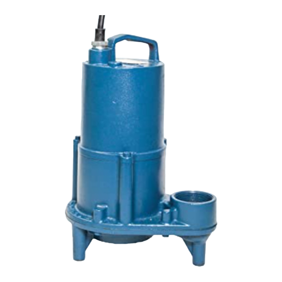
Submersible Septic Tank Effluent Pump
IMPORTANT!
Read all instructions in this manual before operating pump.
As a result of Crane Pumps & Systems, Inc., constant product improvement program,
product changes may occur. As such Crane Pumps & Systems reserves the right to
change product without prior written notification.
A Crane Co. Company
420 Third Street
Piqua, Ohio 45356
Phone: (937) 778-8947
Fax: (937) 773-7157
www.cranepumps.com
BARNES
BARNES
Series: STEP-SS & DS
.5 & 1.0 HP, 3450 RPM, 60 Hz.
Single and Double Seal
83 West Drive, Bramton
Ontario, Canada L6T 2J6
Phone: (905) 457-6223
Fax: (905) 457-2650
®
Form No. 105243-Rev. Z
Advertisement
Table of Contents

Subscribe to Our Youtube Channel
Related Manuals for Crane BARNES STEP-SS Series


Summary of Contents for Crane BARNES STEP-SS Series
- Page 1 Read all instructions in this manual before operating pump. As a result of Crane Pumps & Systems, Inc., constant product improvement program, product changes may occur. As such Crane Pumps & Systems reserves the right to change product without prior written notification. A Crane Co. Company...
-
Page 2: Table Of Contents
PRESSURE GAUGE KIT (see parts list) Other brand and product names are trademarks or registered trademarks of their respective holders. ® Barnes is a registered trademark of Crane Pumps & Systems, Inc 1999, 2002, 1/2004, 5/04, 8/05, 4/06, 9/06 Alteration Rights Reserved... -
Page 3: Safety First
WARNING! - DO NOT pump hazardous materials IMPORTANT! - Crane Pumps & Systems, Inc. is not (flammable, caustic, etc.) unless the pump is specifically responsible for losses, injury, or death resulting from a designed and designated to handle them. -
Page 4: Pump Specifications
SECTION: A - PUMP SPECIFICATIONS- Single Seal: DISCHARGE ....2” NPT, Vertical, Bolt-on Flange UPPER BEARING ..Single Row, Ball, Oil lubricated LIQUID TEMP ....104°F (40°C) Continuous LOWER BEARING ..Single Row, Ball, Oil lubricated VOLUTE ....Cast Iron ASTM A-48, Class 30 MOTOR: Design ... - Page 5 SECTION: A - PUMP SPECIFICATIONS- Double Seal: DISCHARGE ....2” NPT, Vertical, Bolt-on Flange UPPER BEARING ..Single Row, Ball, Oil lubricated LIQUID TEMP ....104°F (40°C) Continuous LOWER BEARING ..Single Row, Ball, Oil lubricated VOLUTE ....... Cast Iron ASTM A-48, Class 30 MOTOR: Design ...
-
Page 6: General Information
For the location of the nearest Barnes Service Center, check Contact your local Barnes distributor for complete details. your Barnes representative or Crane Pumps & Systems, Inc., Service Department in Piqua, Ohio, telephone (937) 778-8947 Stainless Rail Package (Not Shown) - The package system or Crane Pumps &... - Page 7 TYPICAL INSTALLATION WITH WIDE ANGLE 120 Volt 1 Phase LEVEL CONTROL Automatic Manual 240 Volt 1 Phase Automatic Manual FIGURE 2 Figure 2 shows a typical installation for 1 phase 120 and 240 FIGURE 3 volt pump with piggy-back plug for manual and automatic Automatic - Plug float cord into outlet, then plug pump operation.
- Page 8 MODEL NO VOLT/ NEMA FULL LOCKED CORD CORD CORD WINDING RESISTANCE (Nom) START LOAD ROTOR SIZE TYPE Emerson Franklin G.E. CODE AMPS AMPS inch (mm) Main - Start Main - Start Main - Start STEP512SS 120/1 3450 11.9 24.6 14/3 SJTOW 0.375 (9.5) 1.04-7.20 1.47-9.59...
-
Page 9: Start-Up Operation
In the event of a moisture detect, check the individual moisture Inspect motor chamber for oil level and contamination sensor probe leads for continuity, (∞ resistance = no moisture) and repair as required per section F-1. and the junction box/control box for moisture content. The Inspect impeller and body for excessive build-up or above situations may induce a false signal in the moisture clogging and repair as required per section F-2. - Page 10 F-1.3) Pressure Test: motor as an air space must remain in the top of the motor Pumps that have had the oil drained from the Motor housing to compensate for oil expansion (see Figures 17 & Housing - Apply pipe sealant to pressure gauge assembly 19).
- Page 11 FIGURE 6 F-2.2) Reassembly: To install impeller (33), clean the threads with thread locking compound cleaner. Apply removable Loctite® 603 or equivalent to shaft threads. Screw impeller onto the shaft hand tight while using a screwdriver in the slot at the end of the shaft to hold it stationary.
- Page 12 F-3.2) Reassembly: It is extremely important to keep seal faces clean during assembly. Dirt particles lodged between these faces will cause the seal to leak. Place spring (28c) over shaft and in place on rotating member (28b), making sure it is seated on retainer and not cocked or resting on bellows tail.
- Page 13 Position unit upright, using blocks to avoid resting unit on on the opposite side of the cable entry bosses of the motor shaft. Unscrew cable hex bolts (11) and remove compression housing (6). Reconnect capacitor leads. Torque motor tie bolts flange (16a) and power cord (16).
-
Page 14: Electrical Data
FIGURE 15 F-4.4) Cord Assemblies: G-3 MODEL NUMBER: Power/Control Cord - Refill the cooling oil as outlined in This designation consists of numbers and letters which paragraph F-1.3. Make wire connections as outlined in represent the discharge size, series, horsepower, motor paragraph F-4.3. - Page 15 FIGURE 16 - CONTIUED...
-
Page 16: Trouble Shooting
TROUBLE SHOOTING CAUTION ! Always disconnect the pump from the electrical power source before handling. If the system fails to operate properly, carefully read instructions and perform maintenance recommendations. If operating problems persist, the following chart may be of assistance in identifying and correcting them: MATCH “CAUSE”... -
Page 17: Single Seal - Cross-Section (Fig. 17)
STEP-SS - Single Seal FIGURE 17... -
Page 18: Single Seal - Exploded View (Fig. 18)
STEP-SS - Single Seal FIGURE 18... -
Page 19: Double Seal - Cross-Section (Fig. 19)
STEP-DS - Double Seal FIGURE 19... -
Page 20: Double Seal - Exploded View (Fig. 20)
STEP-DS - Double Seal FIGURE 20... -
Page 21: Parts List
PARTS KITS Seal Repair Kits: Single Seal ....P/N - 130180 (+) 20, 27, 28, 36, 57 Double Seal ...P/N - 130176 (†) 20, 27, 28, 32, 36, 57 Service Kits: Single Seal .....P/N - 130207 (◊) 19, 20, 22, 24, 25, 27, 28, 36, 49, 57, 65 Double Seal ...P/N - 130172 () 19, 20, 22, 24, 25, 27, 28, 32, 36, 44, 49, 57, 65 Seal Tool Kit ....P/N - 107271... - Page 22 Impeller, Polypropylene 103512 5.25 Dia. (STD for 1.0 HP) 103512TA 5.13 Dia. 103512TB 5.00 Dia. 103512TC 4.88 Dia. 103512TD 4.75 Dia. 103512TE 4.63 Dia. (STD for .5 HP) 103512TF 4.50 Dia. 103512TG 4.38 Dia. 103512TH 4.25 Dia. 103512TJ 4.13 Dia. 103512TK 4.00 Dia.
-
Page 23: Notes
Notes... - Page 24 Notes...
-
Page 25: Warrant
IMPORTANT! WARRANTY REGISTRATION Your product is covered by a warranty: www.cranepumps.com/downloadables/CATALOGS_OIPMs/Warranty/24MonthWarranty.pdf If you have a claim under the provisions of the warranty, contact your local Crane Pumps & Systems, Inc. Distributor.
Need help?
Do you have a question about the BARNES STEP-SS Series and is the answer not in the manual?
Questions and answers