Table of Contents
Advertisement
Quick Links
Advertisement
Table of Contents

Related Manuals for BK Precision MR Series


Summary of Contents for BK Precision MR Series
- Page 2 Safety Summary The following safety precautions apply to both operating and maintenance personnel and must be followed during all phases of operation, service, and repair of this instrument. Before applying power to this instrument: • Read and understand the safety and operational information in this manual. •...
- Page 3 Electrical Power This instrument is intended to be powered from a CATEGORY II mains power environment. The mains power should be 115 V RMS or 230 V RMS. Use only the power cord supplied with the instrument and ensure it is appropriate for your country of use.
- Page 4 Do not operate instrument if damaged If the instrument is damaged, appears to be damaged, or if any liquid, chemical, or other material gets on or inside the instrument, remove the instrument’s power cord, remove the instrument from service, label it as not to be operated, and return the instrument to B&K Precision for repair.
- Page 5 Do not substitute parts that are not approved by B&K Precision or modify this instrument. Return the instrument to B&K Precision for service and repair to ensure that safety and performance features are maintained. For continued safe use of the instrument •...
- Page 6 CE Declaration of Conformity This instrument meets the requirements of 2006/95/EC Low Voltage Directive and 2004/108/EC Electromagnetic Com- patibility Directive with the following standards. Low Voltage Directive – UL 61010-1:2012 EMC Directive – EN 55011:2009+A2:2010 – EN 61000-3-11: 2000 – EN 61000-3-12: 2011 –...
-
Page 7: Table Of Contents
Contents Introduction Product Overview Contents Features Dimensions Front Panel Display Rear Panel Getting Started Input Power and Fuse Requirements Fuse Replacement Rackmount Installation Output Connections Preliminary Check 2.5.1 Verify AC Input Voltage 2.5.2 Connect Power 2.5.3 Warm-Up Time 2.5.4 Output Check Front Panel Operation Menu Options 3.1.1... - Page 8 Parallel Operation Connection and Setup Slave Unit Master Unit PV Simulation Power- On State Communication Configuration 7.1.1 USBVCP 7.1.2 USBTMC RS232 GPIB RS485 LAN (Ethernet) 7.5.1 Web Server Error/Event List System Menu Enable/Disable Key Sound Error Log Restore Factory Default Settings Save/Recall Instrument Settings 8.4.1 Save Settings...
-
Page 9: Introduction
The MR series power supplies also provide over voltage protection (OVP) and over current protection (OCP) features used to keep the output voltage and current within a specified safety level and preventing damage to the UUT (Unit Under Test). -
Page 10: Dimensions
Introduction • High power output of up to 5000 watts (0-160V/120A) (0-250V/80A) (0-500V/40A) (0-1000V/20A) • USBVCP(virtual COM)/USBTMC/RS232/RS485/Analog/GPIB and Ethernet interfaces • Parallel connectivity for up to *50 units • Adjustable voltage and current slope • 9 user defined programs with up to 100 steps each •... -
Page 11: Display
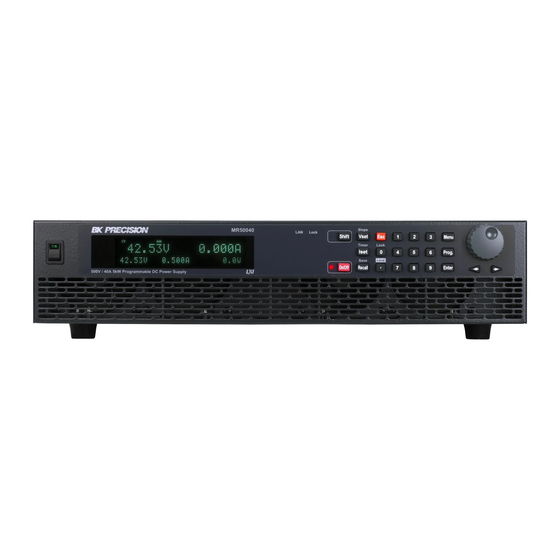
Introduction 1.6 Display Figure 1.3 Display Item Description Measured voltage Settings voltage and current Measured power output Measured current Indicates output is disabled Indicates constant current (CC) operation Indicates constant voltage (CV) operation Indicates remote mode Addr Indicates remote communication activity Error Indicates an error has occurred Shift Indicates shift mode (access to secondary button functions) -
Page 12: Getting Started
Getting Started Before connecting and powering up the instrument, please review and go through the instructions in this chapter. 2.1 Input Power and Fuse Requirements The supply has a universal AC input that accepts line voltage input within: Model MR3K160120 MR160120 MR25080 MR50040 MR100020... - Page 13 Getting Started Figure 2.1 AC Power Connection Diagram Refer to the descriptions below to connect the other end of the AC power cord to the AC distribution panel. Do NOT plug the AC power cord into the wall socket prior to connecting ALL three AC power wires to the rear panel and securely mount the safety metal housing over the input receptacle.
-
Page 14: Fuse Replacement
2.3 Rackmount Installation The MR series power supplies are designed to fit in a space of two rack units (2U) and can be mounted in a standard 19-inch rack panel or cabinet. Rack mount brackets must be assembled before mounting the unit in a rack. Refer to the following figure to assemble the rack mount brackets. -
Page 15: Output Connections
Figure 2.4 Power On Display 2.5.3 Warm-Up Time The MR series is fully operable upon switching the power ON. However, to reach the specified equipment accuracy, please allow the supply to warm up for at least 15 minutes. 2.5.4 Output Check... - Page 16 Getting Started 1. Voltage Check – Turn ON the power supply. The display will show the OFF annunciator above the voltage display. – Enable the output by pressing . After pressing the button the LED next to the button will be lit. The OFF annunciator will change to CV.
- Page 17 Getting Started – The model is shown above as MR160120. – Press twice again and the firmware version will displayed. – The UI firmware is shown above as 1.02. – Press once again and the firmware version will displayed. – The control firmware is shown above as 1.02. –...
-
Page 18: Front Panel Operation
Front Panel Operation Figure 3.1 Menu Tree 3.1 Menu Options All settings and parameters can be configured from the built-in menu system of the power supply. To access the menu, press The menu system is divided into 5 sections and are organized as follows: 3.1.1 Configuration Configures voltage setting limits. -
Page 19: Power-On State
Front Panel Operation 3.1.4 Power-On State Configure power-on state. 3.1.5 COMMUNICATION USB TMC/VCOM GPIB RS485 RS232 3.1.6 System Beep Enable/Disable key sound. Information Shows model, firmware version, communications settings, optional modules install and other power supply information. Calibration Calibration menu. Default Select memory location for save/recall instrument settings. -
Page 20: Configure Voltage/Current Output
Front Panel Operation 6. There may be parameters or options to select within each menu item. Follow the same instructions as described in the previous steps to select them. To save changes to a setting, press 7. To exit the menu at any time, press until the normal. -
Page 21: Local Sense
Front Panel Operation 3.3.3 Local Sense By default, the power supply is set up for local sense. See the figure for the Remote and Local Sense setup. Figure 3.2 Local Sense When local sense is selected, the positive lead (+) of the DC output is connected to the positive end (+) of the load and the negative lead (-) of the DC output is connected to the negative end (-) of the load. -
Page 22: Voltage/Current Measurement
Front Panel Operation DO NOT at any time disconnect the wires from the Vs+ and Vs- terminals to the DUT while output is enabled (ON). Doing so may damage the power supply and cause unstable output. 3.4 Voltage/Current Measurement The display will show the set voltage and current values and the measured values of the output. System Messages The MR has built-in sensors to detect system conditions. -
Page 23: Config Menu
Front Panel Operation 3.5 Config Menu All setup procedures and settings explained in this section can be accessed from the CONFIGURATION menu. To access this menu, press , select CONFIGURATION, then press 3.5.1 Output Limit Settings The voltage or current output limits can be configured to provide limit protection to prevent accidental changes to the output settings. -
Page 24: Over Current Protection (Ocp)
Front Panel Operation 3. Use numerical keys directly or use keys with the rotary knob to adjust the value. Press to confirm the OVP value. 4. Press several times to exit the menu setting. When OVP protection is tripped during operation, the output will turn off and the following OVP status message will display: To clear the trip status, press once. -
Page 25: Over Power Protection (Opp)
Front Panel Operation 3.5.4 Over Power Protection (OPP) The MR overpower protection continuously monitors the output power. If it is greater than the OPP setting, it turns off the power supply output to protect the device under test. Follow the steps below to set the OPP limit: 1. -
Page 26: Cc To Cv Protection
Front Panel Operation To clear the trip status, press once. 3.5.6 CC to CV Protection The MR CC to CV protection monitors the transition between constant voltage to constant current mode. If this event occurs, the output of the power supply will turn off. Follow the steps below to set the CC to CV limit: 1. - Page 27 Front Panel Operation Figure 3.3 DB25 Pinout Signal Description Open: Output is OFF Enable Short to ground: Output is ON Ground Ground Local/Analog Open: Front panel control Short to ground: Rear analog control Input 0-5 V / 0-5 kΩ or 0-10 V / 0-10 kΩ for voltage output setting, full scale Voltage Program input equals maximum output voltage Input 0-5 V / 0-5 kΩ...
-
Page 28: External Control Settings
Front Panel Operation 3.5.8 External Control Settings If you want to use the external mode to control the power, you must enter the menu configures external analog control before entering the external mode. Follow the steps below: • Press the button, select CONFIGURATION, then press •... -
Page 29: Voltage Program
Front Panel Operation Power OK Signal Pin 16 is used to indicate whether a fault condition is present in the power supply. Normally this pin will output a logic high (5V). When a fault occurs, this pin will output a logic low (0V). Fault conditions are defined as follows: 1. -
Page 30: Resistor Mode
Front Panel Operation Current Program Under voltage mode, the user may control the full scale current output value through Pin 10, by inputting a voltage level of 0-5V (0-5 V / 0-5 kΩ mode) or 0-10V (0-10 V / 0-10 kΩ mode) as shown below. Figure 3.5 Voltage Mode Current Program: 0-5 V or 0-10 V 3.7.1 Resistor Mode Under resistor mode, the user may control the full scale voltage output value by connecting a resistance value of 0-5 kΩ... -
Page 31: Voltage Monitor
Front Panel Operation 3.7.1 Voltage Monitor This function is able to monitor the voltage output using Pin 11 and one of the ground pins (i.e. Pin 22), which can be connected to a digital voltage meter (DVM) or other voltage monitoring device, as shown below. The output control must be in analog mode to use this function. -
Page 32: Parallel Operation
Parallel Operation The MR power supplies can be connected in parallel to increase the power output capability as well as the output current. Up to *50 units of the same model can be connected for output up to 250 kW (max). 4.1 Connection and Setup To connect multiple units in parallel, follow the diagram shown below: Figure 4.1 Connection and Setup... -
Page 33: Slave Unit
Parallel Operation 4. Press the button one time until Address is select and press 5. Use the rotary knob to set the master or slave and press . Use the same procedure to set up MASTER, SLAVE 1, SLAVE 2,…,SLAVE 49 for the other power supplies. 6. - Page 34 Parallel Operation While in parallel connection mode, the output voltage of each power supply should be set to equal value. If the voltage value of each unit is not the same, the higher output voltage will feed back to the lower voltage unit and damage its internal components.
-
Page 35: Pv Simulation
PV Simulation Typically, a solar array is connected to an inverter, which converts the panel’s output from DC to AC. Due to varying environmental conditions and the nonlinear output of solar cells, many inverters use a maximum power point tracking mechanism to maximize the power generated from the solar panel. - Page 36 PV Simulation the SAS software. The SAS software also monitors and logs real-time voltage, current, and power as well as real-time and average MPPT efficiency to validate the inverter’s MPPT algorithm. To configure and set the MR power supply to PV mode from the front panel, follow the steps below: 1.
-
Page 37: Power- On State
Power- On State The initial Power-On state of the power supply can be configured (voltage, current, output state) by the following the steps below: • From the menu, press the button 3 times to select POWER-ON STATE and press • The mode is showing on the display, press the button. -
Page 38: Communication Configuration
.The RMT indicator will disappear when the instrument is in LOCAL mode. 7.1 USB The MR series supports USBVCP and USBTMC. To select either USBVCP or USBTMC: • From the menu, select Communication and press • When USB is select, press to select USB. -
Page 39: Usbtmc
Communication Configuration 7.1.2 USBTMC The USBTMC driver must be installed to use the USBTMC interface. The driver is included in the VISA software download and can also be found on our website. bkprecision.com (We recommend using NI-VISA, which can be downloaded at www.ni.com 7.2 RS232... -
Page 40: Gpib
Communication Configuration 7.3 GPIB Each model can be configured with a GPIB address from 1-30. Follow the instructions below to select and configure the GPIB interface for remote operation. • From the menu, select Communication and press • When GPIB is select, press to configure the settings for GPIB remote communication. - Page 41 7.4 RS485 The MR series supports multiple power supplies (of the same model, up to *50) that can be connected together via RS485. The power supplies can be controlled with a computer via USB (virtual COM) interface (Chain mode). When connecting more than 10 units, add a 120Ω...
- Page 42 Communication Configuration Below lists the options that can be changed for each setting: Baud rate: 9600, 19200, 38400, 57600 Note: The default is 9600, None/8 bits, 1, Address = 1, Off. For each power supply that you want to control, provide a different address. For example, if you have three power supplies to control, set the first supply to address 1, second supply to address 2, and third supply to address 3.
-
Page 43: Lan (Ethernet)
Communication Configuration True RS485 The RS485 port is true RS485 mode by default allowing it to be used as an I/O interface for remote control and programming when parallel and chain mode are disabled. The following table shows under what conditions true RS485 mode can be enabled: Condition True RS485 mode Parallel mode... - Page 44 Communication Configuration IP Address The IP Address is a unique string of numbers separated by periods. To enter an IP address: Use the numeric keypad to enter an IP address. Then keys are used to separate each number in the string. After inputting each number press to set the address.
-
Page 45: Web Server
Communication Configuration 7.5.1 Web Server There is an embedded web server GUI that can access the power supply via LAN interface using a web browser. The GUI provides a simple way of setting voltage and current, as well as monitoring the output, using a web browser from a computer connected to the same local area network as the power supply. - Page 46 Communication Configuration Home Page The HOME page provides general information of the power supply: LXI Device Model, Manufacturer, Serial Number, Description, LXI Version, mDNS Hostname, MAC address, TCP/IP address, Firmware Version, LXI Extended Function, LXI Device Address String, TCP/IP SOCKET Device Address String, USBTMC Device Address String, GPIB Device Address String, USB Port Function, RS232C setting, RS485 setting, Identification indicator function.
- Page 47 Communication Configuration LAN Configuration The LAN CONFIG page provides the Hostname, Description, IP Address, IP Address, Netmask, Gateway, DNS, password, Lan configuration, initialize, Restore Factory Settings. Figure 7.3 LAN Configuration...
- Page 48 Communication Configuration Parameter Configuration The CONFIG page provides the protection settings (OVP, OCP, OPP, CV to CC, and CC to CV) and output related parameters such as voltage/current slope and limit settings. Figure 7.4 Parameters Configuration...
- Page 49 Communication Configuration Control Page The CONTROL page provides the general control of the power supply such as output On/Off setting as well as the voltage and current setting. The command line for SCPI commands can also be accessed here. Figure 7.5 Control Page...
-
Page 50: Error/Event List
Communication Configuration Socket Connection Socket connection is available for communication via LAN (Ethernet) interface. The instrument uses the TCP/IP protocol for communication. Users can use socket port 5025 to open a raw socket connection for sending remote commands. 7.6 Error/Event List SCPI interface can offer an error/event list that contains up to 20 errors/events. -
Page 51: System Menu
System Menu All setup procedures and settings explained in this section can be accessed from the SYSTEM menu. To access this menu, press and press the button five times until SYSTEM is displayed. Press the button to enter the menu. 8.1 Enable/Disable Key Sound By default the key sound is enabled. -
Page 52: Restore Factory Default Settings
System Menu Error Code Definition Error Code Definition B001 Buck BUS Error P001 PFC Over current D001 Control board EEPROM Error P002 PFC board no response F001 AC Input Freq. Error P003 PFC BUS low H001 H/W OVP fail P004 PFC BUS High H002 H/W OCP fail... - Page 53 System Menu Item Parameter MR160120 MR3K160120 MR25080 MR50040 MR100020 Voltage Output Current State OVP Voltage 1100 OCP Current Protection OPP Power 5200.5 3120 5200.5 5200.5 5200.5 CV to CC CC to CV Vmax 163.2 163.2 1020 Vmin Limit Imax 122.4 122.4 81.6 40.8...
-
Page 54: Save/Recall Instrument Settings
System Menu 8.4 Save/Recall Instrument Settings The instrument can save up to 10 voltage/current values for quick recall. 8.4.1 Save Settings 1. Set up output voltage and current settings that you want to save. 2. Then, press followed by . The display will show the following: 3. -
Page 55: Program Function
System Menu 8.5 Program Function The MR has a Program feature that allows storing of programs into internal non-volatile memory and recalling and running them per configured parameters. A total of 100 steps can be configured for each program, and a total of 10 programs are available for storage. -
Page 56: Setup A Program
System Menu Note: REPEAT and NEXT options are part of a program, so if one program’s NEXT option is pointed to a previous program, the power supply will cycle these programs infinitely. 8.5.2 Setup a Program To setup a program: 1. -
Page 57: Timer
System Menu a. Press to edit step, use the keys to move the cursor to the desired parameter and use the rotary knob or keypad (numeric values only) to change the parameter values. b. Press to complete the this step edit. c. -
Page 58: Slew Rate
System Menu 4. Press to complete the timer setting. 5. Pressing the key will enable the output and start the timer. 8.7 Slew Rate The power supply has the capability of controlling the output voltage and current slew rate. The timing can be configured for the rising/falling edge between voltage and current output transitions. -
Page 59: Calibration
Calibration B&K Precision recommends a calibration interval of one year to ensure that the power supply meets specifications. This instrument features closed-case calibration. To perform the calibration, the following equipment is required: • 6 ½ digit digital multimeter (DMM); B&K Precision 5493C or equivalent The following calibration instructions may be used by authorized technicians or calibration personnel only. -
Page 60: Voltage Calibration
Calibration These options are only accessible in the calibration menu. The following calibration procedures assume the operator is in the CAL menu. 9.1 Voltage Calibration To perform a voltage calibration: 1. Connect the DMM to the output of the power supply as shown in the figure below: Figure 9.1 Voltage Calibration Diagram When only calibrate local sense, connect the DMM to the output. -
Page 61: Current Calibration
Calibration 9.2 Current Calibration To perform a current calibration: • Connect the shunt resistance, DMM and Electronic load to the output of the power supply as shown in the figure below: Figure 9.2 Current Calibration Diagram • Set the DMM to a DC voltage measurement. Set the Electric Load in CV mode, the voltage set 5V. Select the CURRENT parameter in the CALIBRATION menu and press . -
Page 62: Ovp Calibration
Calibration 9.3 OVP Calibration The overvoltage protection (OVP) calibration can be executed right after the voltage calibration or the user can select OVP in the Calibration menu. To perform the overvoltage protection calibration: 1. Disconnect any load from the output terminal of the power supply. 2. -
Page 63: Ocp Calibration
Calibration 9.4 OCP Calibration The overcurrent protection (OCP) can be executed right after the current calibration or the user can select OCP in the Calibration menu. To perform the voltage calibration: 1. Short the output + and - terminals of the power supply as shown below: Figure 9.3 OCP Calibration Diagram 2. -
Page 64: External Voltage Programming Calibration
Calibration 9.5 External Voltage Programming Calibration To perform the external voltage programming calibration: 1. Connect the DMM to the external analog control terminals of DB25 connector (+ on the DMM to Pins 9 and 11, - on the DMM to Pin 22 (GND)) on the rear of the power supply, as shown in the figure below: Figure 9.4 External Voltage Programming Calibration Diagram 2. -
Page 65: External Current Programming Calibration
Calibration 9.6 External Current Programming Calibration To perform the external current programming calibration: 1. Connect the DMM to the external analog control terminals of DB25 connector (+ on the DMM to Pins 10 and 24, - on the DMM to Pin 22(GND)) on the rear of the power supply, as shown in the figure below: Figure 9.5 Current Programming Calibration Diagram 2. -
Page 66: Cc Calibration Of External Voltage
Calibration 9.7 CC Calibration of External Voltage To perform the calibration procedure for the constant current source of the external voltage programming by resistor mode: 1. Connect the external analog control terminals of DB25 connector (Pins 9, 22(GND)) on the rear of the power supply, as shown in the figure below: Figure 9.6 CC Calibration of External Voltage Diagram 2. -
Page 67: Cc Calibration Of External Current
Calibration 9.8 CC Calibration of External Current To perform the calibration procedure for the constant current source of the external current programming by resistor mode: 1. Connect the external analog control terminals of DB25 connector (Pins 10, Pin 22(GND)) on the rear of the power supply, as shown in the figure below: Figure 9.7 CC Calibration of External Current Diagram 2. -
Page 68: Specifications
Specifications... - Page 69 Specifications...
-
Page 70: Service Information
Service Information Warranty Service: Please go to the support and service section on our website at bkprecision.com to obtain an RMA #. Return the product in the original packaging with proof of purchase to the address below. Clearly state on the RMA the performance problem and return any leads, probes, connectors and accessories that you are using with the device. -
Page 71: Limited Three-Year Warranty
LIMITED THREE-YEAR WARRANTY B&K Precision Corp. warrants to the original purchaser that its products and the component parts thereof, will be free from defects in workmanship and materials for a period of three years from date of purchase. B&K Precision Corp. will, without charge, repair or replace, at its option, defective product or component parts. Returned product must be accompanied by proof of the purchase date in the form of a sales receipt.
Need help?
Do you have a question about the MR Series and is the answer not in the manual?
Questions and answers