Table of Contents
Advertisement
Quick Links
Advertisement
Table of Contents

Related Manuals for BK Precision 1697B


Summary of Contents for BK Precision 1697B
- Page 2 Safety Summary The following safety precautions apply to both operating and maintenance personnel and must be followed during all phases of operation, service, and repair of this instrument. Before applying power to this instrument: • Read and understand the safety and operational information in this manual. •...
- Page 3 Electrical Power This instrument is intended to be powered from a CATEGORY II mains power environment. The mains power should be 115 V RMS or 230 V RMS. Use only the power cord supplied with the instrument and ensure it is appropriate for your country of use.
- Page 4 Do not operate instrument if damaged If the instrument is damaged, appears to be damaged, or if any liquid, chemical, or other material gets on or inside the instrument, remove the instrument’s power cord, remove the instrument from service, label it as not to be operated, and return the instrument to B&K Precision for repair.
- Page 5 Do not substitute parts that are not approved by B&K Precision or modify this instrument. Return the instrument to B&K Precision for service and repair to ensure that safety and performance features are maintained. For continued safe use of the instrument •...
- Page 6 Safety Symbols Symbol Description indicates a hazardous situation which, if not avoided, will result in death or serious injury. indicates a hazardous situation which, if not avoided, could result in death or serious injury indicates a hazardous situation which, if not avoided, will result in minor or moderate injury Refer to the text near the symbol.
-
Page 7: Table Of Contents
Contents IMPORTANT SAFETY INSTRUCTIONS Precautions Product Overview Package Contents Power Requirements Interface and Controls Basic Operation Setting Voltage and Current by Rotary Knob and Up/Down Keys Setting Voltage and Current Using Keypad Operating Instructions Output Enable Output Disable Locking the Keypad and Rotary Knob Unlocking the Keypad and Rotary Knob Setting the RS-485 Address Setting the Upper Voltage Limit... -
Page 8: Important Safety Instructions
IMPORTANT SAFETY INSTRUCTIONS 1. Do not use this apparatus near water. 2. Clean only with dry cloth. 3. Do not block any ventilation openings. 4. Do not install unit near any heat source or heating emitting devices. 5. Prevent the power cord from being walked on or pinched. 6. -
Page 9: Product Overview
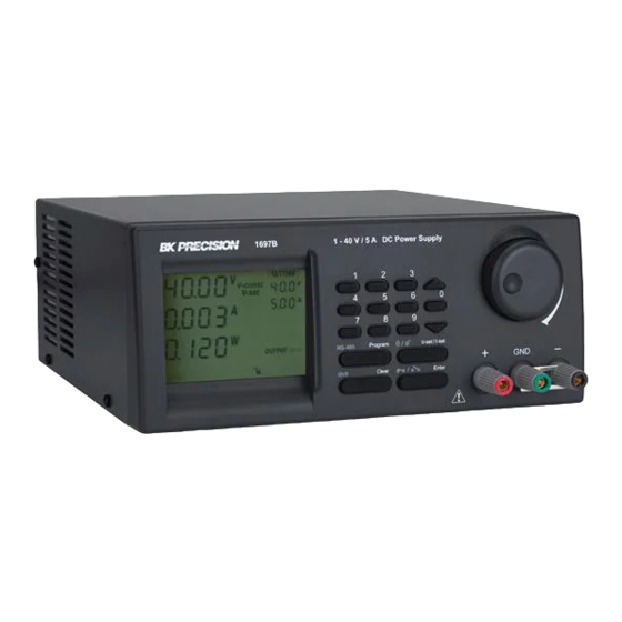
Product Overview 2.1 Package Contents • Power Supply (1696B, 1697B or 1698B) • Power cord • USB cable 2.2 Power Requirements Parameter Value Voltage 100 - 240 VAC Frequency 50/60 Hz Fuse 4A Slow Blow 250V 2.3 Interface and Controls... -
Page 10: Basic Operation
Basic Operation 3.1 Setting Voltage and Current by Rotary Knob and Up/Down Keys 1. Press to switch between setting voltage and current. 2. Rotate control knob or press to set voltage/current level. Press the control knob to toggle the cursor position. 3.2 Setting Voltage and Current Using Keypad 1. -
Page 11: Operating Instructions
Operating Instructions 4.1 Output Enable 1. Press 2. Press within 3 seconds to ENABLE output 4.2 Output Disable 1. Press 2. Press within 3 seconds to DISABLE output 4.3 Locking the Keypad and Rotary Knob 1. Press 2. Press within 3 seconds to lock keypad and rotary knob 4.4 Unlocking the Keypad and Rotary Knob 1. -
Page 12: Enable Output At Power Up
Operating Instructions 3. Use the numeric keypad to input upper voltage limit. 4. Press to confirm. 4.7 Enable Output at Power Up This feature limits the upper level setting of output voltage to prevent inadvertent setting of high voltage, which may damage your application. -
Page 13: Using Programming Features
Using Programming Features 5.1 Preset Program 1. Press Program 2. Use the numeric keypad thru to select a preset voltage and current value. 3. Use to adjust preset voltage and current values. 4. Press within 3 seconds to confirm or press to exit program setting. -
Page 14: Maintenance
Maintenance 6.1 Recalibration The purpose of recalibration is to reduce the difference between the set values and the displayed values on the LCD display. Recalibration is only required when this difference is greater than 0.1 V for voltage or -0.01 A / +0.02 A for current. -
Page 15: Pc Software Control And Installation
PC Software Control and Installation The PC software provides remote communication, data logging, front panel emulation, and timed programming capabilities using the USB or RS-485 interfaces. The software supports Windows 7, 8, 8.1, 10. Note: Do not connect both USB and RS-485 simultaneously. 7.1 USB Driver Installation Remote communication using USB requires the installation of the CP210X USB virtual COM driver available for download at bkprecision.com. -
Page 16: Multi-Unit Control
PC Software Control and Installation Figure 7.3 4. Click “Next” to continue. Figure 7.4 Figure 7.4 5. Select a destination location for the software. Figure 7.5 6. Select a location for the software shortcut.Figure 7.6 7. Check the box if you would like to create a desktop shortcut and click “Next” to continue. Figure 7.7 8. -
Page 17: Setup A New Instrument
PC Software Control and Installation Figure 7.5 Figure 7.6 open the PC software. shows the screen to expect when the software starts. If there is already a saved Figure 7.11 connection the software will automatically connect to the instrument. 7.4.1 Setup a new instrument •... - Page 18 PC Software Control and Installation Figure 7.7 Figure 7.8 • Type in a connection name, select USB from the drop down, and select the correct COMM port assigned by your PC. Check the windows the device manager to determine the correct COMM port. In this case Windows has assigned COM port 12.
-
Page 19: Enable Scpi Protocol
PC Software Control and Installation Figure 7.9 Connection diagram for multiple power supply control Figure 7.10 Connection diagram between USB adapter and RS-485 connectors Display Panel 7.4.2 Enable SCPI protocol Press then to enter SCPI setting. Use the rotary knob to select “Y” and press to save and exit. -
Page 20: Internal Preset Memory
PC Software Control and Installation Figure 7.11 Figure 7.12 7.4.5 Internal Preset Memory Preset up to 9 voltage and current combinations into memory for quick output. Set voltage and current with the slider bar and click to confirm. See Figure 7.23 7.4.6 Data Logging Data Log allows can be used to view present or stored output data, see Figure... - Page 21 PC Software Control and Installation Figure 7.13 Figure 7.14 Figure 7.15...
- Page 22 PC Software Control and Installation Figure 7.16 Figure 7.17 SCPI Selection Figure 7.18...
- Page 23 PC Software Control and Installation Figure 7.19 Figure 7.20 Figure 7.21...
- Page 24 PC Software Control and Installation Figure 7.22 Figure 7.23 Figure 7.24 Figure 7.25...
- Page 25 Programmable DC Power Supplies Models 1696B, 1697B & 1698B Specifications Note: All specifications apply to the unit after a temperature stabilization time of 30 minutes over an ambient temperature range of 23 °C ± 5 °C. Model 1696B 1697B 1698B...
-
Page 26: Service Information
Service Information Warranty Service: Please go to the support and service section on our website at bkprecision.com to obtain an RMA #. Return the product in the original packaging with proof of purchase to the address below. Clearly state on the RMA the performance problem and return any leads, probes, connectors and accessories that you are using with the device. -
Page 27: Limited One-Year Warranty
LIMITED ONE-YEAR WARRANTY B&K Precision Corp. warrants to the original purchaser that its products and the component parts thereof, will be free from defects in workmanship and materials for a period of one years from date of purchase. B&K Precision Corp. will, without charge, repair or replace, at its option, defective product or component parts. Returned product must be accompanied by proof of the purchase date in the form of a sales receipt.
Need help?
Do you have a question about the 1697B and is the answer not in the manual?
Questions and answers