
Related Manuals for BK Precision 1785B


Summary of Contents for BK Precision 1785B
- Page 1 Instruction Manual Model 1785B, 1786B, 1787B & 1788 Programmable DC Power Supplies...
-
Page 2: Table Of Contents
1.2 Output Checkout...9 1.2.1 Voltage Output Checkout ...9 1.2.2 Current Output Checkout ...9 1.3 If the Power Supply Does Not Turn On ...10 1.4 To Adjust the Carrying Handle ...10 1.5 To Rack Mount the Instrument ...11 Chapter 2 Specifications ...12 2.1 Specifications...12... -
Page 3: Quick Reference
Quick Reference About your safety Pease review the following safety precautions before operating our equipment. General information The following safety precautions should be observed before using this product and any associated instrumentations. Although some instruments and accessories would be used with non-hazardous voltages, there are situations where hazardous conditions may be present. -
Page 4: Introduction
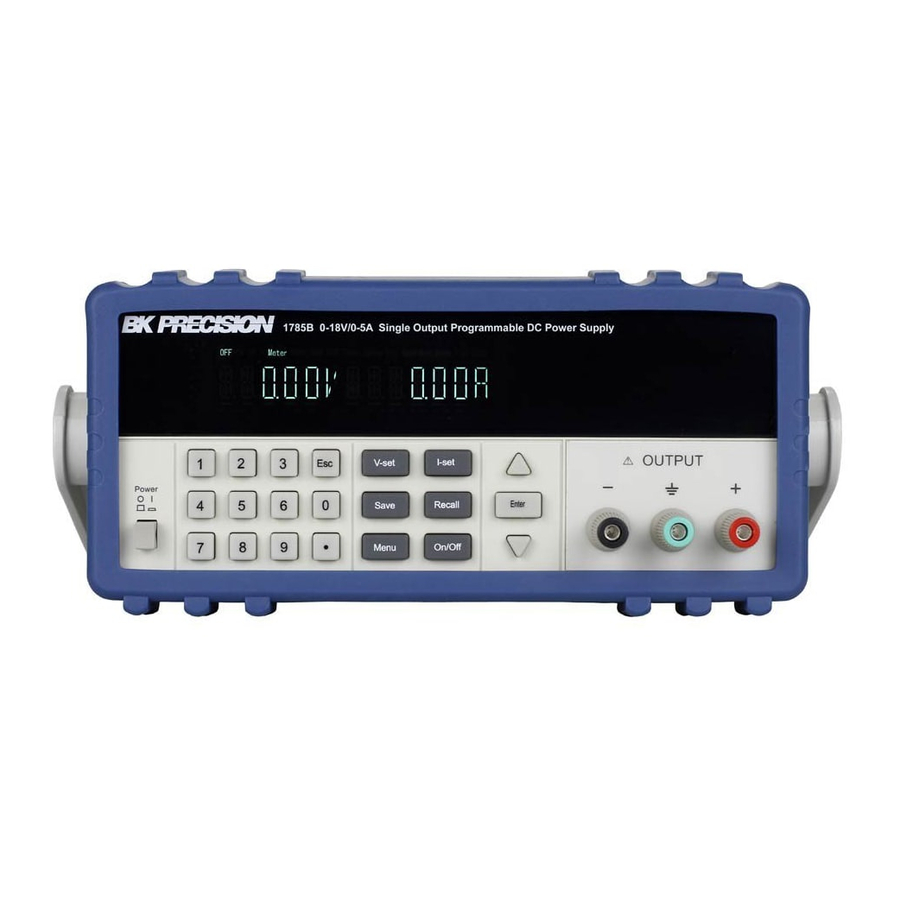
We certify that this product met its published specifications at time of shipment from the factory. Introduction The 1785B - 1788 Series power supplies are high performance single-output programmable DC power supplies with communication interface. The combination of bench-top and system features in these power supplies provides versatile solutions for your design and test requirements. -
Page 5: The Front Panel At A Glance
The Front Panel at a Glance 10 digits VFD display Status information for operating mode and working status Power switch Number keys Function keys UP/DOWN and ENTER key Output terminals... -
Page 6: Function Keys Description
Save the present settings to a specified register location(1~16) Save Recall a saved settings from location ‘‘1’’through ‘‘16’ Recall Menu function to set related parameters of the power supply Menu Output ON/OFF, to enable/disable the output Out on/off Menu description Menu >MAX VOLT... -
Page 7: The Rear Panel At A Glance
The power supply is in constant The power supply is in constant current mode. current mode. Unreg The output of the power supply Unreg The output of the power supply is unregulated (neither CV nor CC) is unregulated (neither CV nor CC) -
Page 8: Chapter 1 Quick Start
Chapter 1 Quick Start One of the first things you will want to do with your power supply is to become acquainted with the front panel. The exercises in this chapter prepare the power supply for use and help you get familiar with some of its front-panel operations. -
Page 9: Output Checkout
Out on/off Notice: if the voltage value flash, then the power supply is in Set mode, ‘‘Set mode’’ means that the VFD display shows the setting output voltage and current. Or the power supply is in Meter mode, ‘Meter mode”... -
Page 10: If The Power Supply Does Not Turn On
3. Verify that the correct power-line fuse is installed. If the fuse was damaged, please see the table below to replace the fuse for your power supply. Fuse Description Fuse 2.5A T 250V for 220VAC Fuse 5A T 250V for 110VAC 1.4 To Adjust the Carrying Handle... -
Page 11: To Rack Mount The Instrument
Carrying position 1.5 To Rack Mount the Instrument You can mount the power supply in a standard 19-inch rack cabinet using the IT-E151 rack mount kit Note: Remove the carrying handle and the two plastic ears before rack-mounting the instrument. -
Page 12: Chapter 2 Specifications
To rack mount two instruments side-by-side, order rack mount kit IT-E151, you needn’t to use the front cover panel. Dimension Chapter 2 Specifications 2.1 Specifications Parameter 1785B 0 ~18V Voltage Output Ratings, 0 ~5A Current ( 0 °C - 40 °C) -
Page 13: Supplemental Characteristics
Voltage Programming Accuracy, 12months, (@ 25 °C ± 5 °C) (% of output+offset) Current Voltage Readback Accuracy 12months, (25 °C ± 5 °C) (% of output+offset) Current Voltage Ripple (20Hz ~20MHz) Current Voltage Temperature Coefficient, (0 °C ~ 40 °C) (% of output+offset) Current Voltage... - Page 14 Environmental Conditions Designed for indoor use in an installation category II, pollution degree 2 environment. Designed to operate at maximum relative humidity of 95% and at altitudes of up to 2000 meters. Weight Type 1785B 1786B 12.3Lbs. 14.8Lbs. 5.6Kg 6.7Kg 14Lbs.
-
Page 15: Chapter 3 Front-Panel Operation
You can change the front-panel and remote operation modes by computer. 3. The power supply is in Meter mode when it is powered on, and the VFD will display the actual voltage and current output value. And in this mode, if any non-functional key is pressed, the power supply will changed to Set mode, and the VFD will display the adjusted voltage and current value. -
Page 16: Constant Current Operation
3.3 Constant Current Operation The constant current output range is from 0A to the maximum current value of each type. It is very easy for you to set the constant current output. Step1. Power on the Power Supply I-Set Step2. Press Step3. - Page 17 This instruction can initiate the output state when the power supply is powered on. If you select ON, the power supply will initiate the output to OFF state when the power supply is powered on. If you select OFF, the output will remain the same state as last time you turned off the power supply Note: Default selection is ON and the output state is always OFF state.
- Page 18 Setting Address (>ADDRESS) This instruction can set the communication address for each power supply. The address range is from 0 to 254. Before the communication, you must make sure that there is same address between the power supply and the computer.
-
Page 19: Chapter 4 Remote Operation Mode
4.1 IT-E131 Communication cable The DB9 interface connector on the rear panel of power supply is TTL voltage level; you can use the communication cable (IT-E131) to connect the DB9 interface connector of the power supply and the RS-232 interface connector of computer for the communication. -
Page 20: Frame Format
OFF state firstly, the command for calibration protection is 27H. When the power supply is in calibration mode, it is not allowed to change the output 4. 4... - Page 21 25 byte byte Note: You can not control the power supply from the front panel when the power supply is in calibration mode. 2. Setting the output state ON/OFF (21H) byte byte byte byte to 25 byte byte 3.
- Page 22 0XE8, 5 6. Setting the communication address (25H) byte byte byte byte to 25 byte byte Reading present voltage/current and the states of power supply. (26H) byte byte byte byte byte byte byte byte byte byte The highest byte of output voltage value...
- Page 23 1. We use 4 bytes to represent the maximum voltage value as follows: Byte 3 Byte 2 Byte1 2. We use 1 byte to represent power supply’s state. Each bit is defined as follows: From higher bit to lower bit 0 bit: The output state, 0 is OFF, 1 is ON.
- Page 24 byte byte byte byte byte byte 10. Calibrating the voltage value (29H) byte byte byte byte to 25 byte byte Note: To calibrate the 3 points of voltage sequentially. 11. Sending the present output voltage to calibration program (2AH) byte byte byte byte...
- Page 25 Note: To calibrate the 2 points of the current value sequentially. 13. Sending the actual output current to calibration program (2CH) byte byte byte byte byte to 25 byte byte 14. Save the calibration data to EEPROM( 2DH) byte byte byte to 25 byte...
- Page 26 If the local key was enabled, user can press the numeric key 7 to change the remote mode to front panel operation mode and all local keys will work. The return information of command operation in power supply byte byte...
-
Page 27: Chapter 5 Calibration
C0H. Or otherwise, it will return to 80H. Chapter 5 Calibration We suggest you to calibrate the power supply yearly. We provide you a set of calibration software Power Calibration (PC1785B_1788). It is very easy to calibrate the power supply by the calibration software. -
Page 28: Configuration
Before the calibration, please click “Config” button to set the COM interface, address and baud rate. The default Com port is COM, and the default baud rate is 9600. Please make sure that the baud rate and address in the software and in power supply are the same. 5.2 Voltage calibration Step 1: Prepare to use multi-meter to measure the output voltage, and connect the voltage meter to the power supply according to the diagram in the above windows. -
Page 29: Reset To The Default Calibration Settings
5.4 Reset to the default calibration settings In the calibration process, if there is any failure caused by the misreading the voltage value and current value or any other reason, you can use the “Restore” to let the power supply return to the state before calibrating. -
Page 30: Pv1785B_1788 Functions
To set current value, use the rotary knob to set the current value, the setup value and measurement value will be displayed. To make a program of voltage and current values for the power supply, or to set the output value quickly. -
Page 31: 1Configure The System
Model number 1. Model number, it will display the real part number of the field power supply which detected by the computer. (6811/6812/6821/6822/6823……..). 2. Operation status (Operation correct/Check error), if Check error appears here, it means that there is check error for your last operation command. -
Page 32: Setting Voltage And Current
6.3.3 Setting Voltage and current 1. Setting voltage/current by rotary knob Note: Before you set the current and voltage value from the computer, please change the operation mode to PC Control mode by pressing 2. Quickly setting Use mouse to click on the rotary knob and move mouse to change the value. -
Page 33: Program Setting
The power supply’s output will respond to the program. Click “Stop” button to stop sending the program settings to the power supply. The power supply state will return to the state before the program running. Click “Chart” to show the voltage and current chart of the program. -
Page 34: Save And Open
6.3.5 Save and Open To save the program settings, quickly settings, voltage sweep settings and GO/NG settings as PAR file. To open the PAR file for reloading the program settings, quickly settings, voltage sweep settings and GO/NG settings. 6.3.6 Present Voltage/Current Chart 6.3.7. - Page 35 Click here and move to zoom in/out axes or scroll axes To set the Y-Axes Span Vertical marker Horizontal marker XY Value marker Limit range between the minimum value and maximum value. Scroll axes mode Zoom in/out axes mode Zoom out Zoom in Save the chart as a .BMP file.
- Page 36 B&K Precision Corp. warrants to the original purchaser that its product and the component parts thereof, will be free from defects in workmanship and materials for a period of one year from the data of purchase. B&K Precision Corp. will, without charge, repair or replace, at its’ option, defective product or component parts.
- Page 37 Service Information Warranty Service: Please return the product in the original packaging with proof of purchase to the below address. Clearly state in writing the performance problem and return any leads, connectors and accessories that you are using with the device. Non-Warranty Service: Return the product in the original packaging to the below address.
- Page 38 PN: 481-534-9-001 Printed in China 2005 B&K Precision Corp. 22820 Savi Ranch Parkway Yorba Linda, CA 92887 TEL: 714-921-9095 FAX: 714-921-6422 www.bkprecision.com...
Need help?
Do you have a question about the 1785B and is the answer not in the manual?
Questions and answers