BK Precision 1688B Instruction Manual
Switching dc power supply
Hide thumbs
Also See for 1688B:
- Instruction manual (41 pages) ,
- Programming manual (15 pages) ,
- Instruction manual (42 pages)
Table of Contents
Advertisement
Quick Links
Advertisement
Table of Contents

Subscribe to Our Youtube Channel
Related Manuals for BK Precision 1688B


Summary of Contents for BK Precision 1688B
- Page 1 Model 1685B, 1687B, 1688B Switching DC Power Supply INSTRUCTION MANUAL...
-
Page 3: Safety Summary
Safety Summary The following safety precautions apply to both operating and maintenance personnel and must be observed during all phases of operation, service, and repair of this instrument. Before applying power, follow the installation instructions and become familiar with the operating instructions for this instrument. - Page 4 WARNINGS AND CAUTIONS WARNING and CAUTION statements, such as the following examples, denote a hazard and appear throughout this manual. Follow all instructions contained in these statements. A WARNING statement calls attention to an operating procedure, practice, or condition, which, if not followed correctly, could result in injury or death to personnel.
- Page 5 Compliance Statements Disposal of Old Electrical & Electronic Equipment (Applicable in the European Union and other European countries with separate collection systems) This product is subject to Directive 2002/96/EC of the European Parliament and the Council of the European Union on waste electrical and electronic equipment (WEEE), and in jurisdictions adopting that Directive, is marked as being put on the market after August 13, 2005, and should not be disposed of as...
-
Page 6: Table Of Contents
Contents Safety Summary ..................1 Introduction ....................6 Controls and Indicators ................7 Front Panel ..................7 Rear Panel ..................8 Operating Instructions ................9 Using the Power Supply ..............10 4.1.1 Connection ................10 4.1.2 Self Test Sequence ..............10 4.1.3 Control Knobs ................ - Page 7 5.1.1 Using Two External Variable DC Voltage Sources ....20 5.1.2 Using Two 5 kΩ Variable Resistors .......... 21 5.1.3 Enable and Disable the Output ..........23 PC Interface Control ................ 23 Faults and Troubleshooting ..............24 OVP: Overvoltage Protection ............24 OTP: Overtemperature Protection ..........
-
Page 8: Introduction
Introduction B&K Precision models 1685B, 1687B, and 1688B are laboratory grade switching mode DC power supplies with high current output in a small form factor and lightweight package. The 1685B Series provides various configurations of output voltage and current, and makes setting voltage and current levels fast and precise through its dual action, coarse/fine rotary encoder control knobs. -
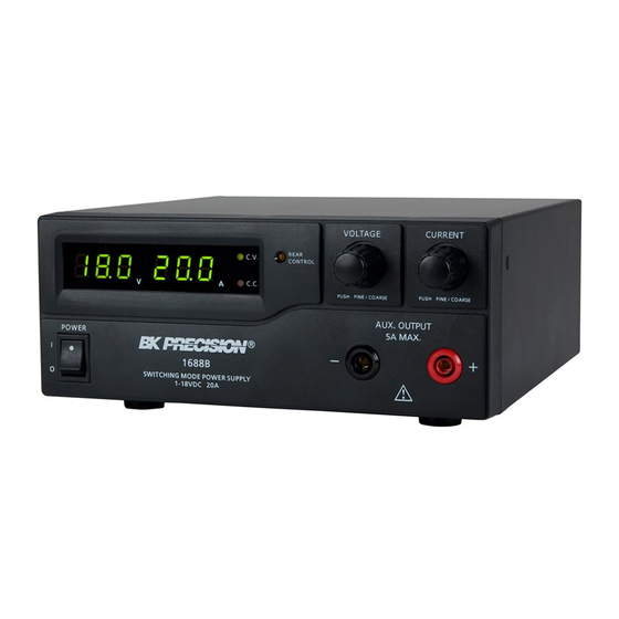
Page 9: Controls And Indicators
Controls and Indicators Front Panel Figure 1 - Front Panel LED panel meter display with CV/CC indicator Rear Control Indicator (lights up when using Preset/Remote Control/Set mode) Output Voltage Control Knob (control main and auxiliary output voltage) Output Current Control Knob (control main and auxiliary output current limit) Power ON/OFF Switch Auxiliary Output Terminal (max 5 A) Note:... -
Page 10: Rear Panel
Rear Panel Figure 2 - Rear Panel Main Output Terminal (max 5 A for 1685B / 10 A for 1687B / 20 A for 1688B) Note: Please see Section 4.1.5 for more details on using both main and auxiliary output terminals together. -
Page 11: Operating Instructions
Model Number Output Voltage Range Total Rated Current 1685B 1 – 60 V 0 – 5 A 1687B 1 – 36 V 0 – 10 A 1688B 1 – 18 V 0 – 20 A Table 1 - Model Table... -
Page 12: Using The Power Supply
Using the Power Supply 4.1.1 Connection To connect the equipment to the power supply, follow the steps below. 1. Check the rating label of the power supply and confirm that it complies with your AC mains voltage. 2. Connect the power supply to the AC mains using the provided power cord and make sure the Mode Selection Switch is in the Normal position. - Page 13 Front Panel Display Test Segment check Constant Voltage mode indicator check Constant Current mode indicator check Rear control indicator check Return to Constant Voltage mode Start power supply checks Overvoltage protection check Overload protection check...
-
Page 14: Control Knobs
Front Panel Display Test Overtemperature protection check Fan check Output off (remote control mode) Table 2 - Self Test Sequence The LED and other indicators on the front panel will be turned on. When the cooling fan is being checked, a loud fan noise can be heard. After the self-checks, the CV, V, and A LED indicators are lit up displaying voltage and 0.0 current. -
Page 15: Manually Zeroing Current Meter Offset
4.1.4 Manually Zeroing Current Meter Offset The power supply will automatically zero the current meter offset when powered up. In case it is needed to reset the current meter to zero during a test, you can manually reset it to zero. This function can be used to zero meter readings < 1 A. 1. -
Page 16: Using Both Main And Auxiliary Outputs
For example, setting the voltage and current outputs for model 1688B (1-18 V, 0-20 A) to 18 V and 20 A would output 18 V at both main and auxiliary terminals and allow you to draw up to a total of 20 A between the two terminals. -
Page 17: Normal Mode
To select a mode, slide the Mode Selection Switch on the rear of the unit. Figure 3 – Mode Selection Switch Note: The power supply is factory preset to Normal Mode with maximum current level. 4.2.1 Normal Mode This is the factory preset mode and the power supply output voltage and current are controlled by the dual action dial knobs. -
Page 18: Analog Remote Control Mode
13.8 V Maximum Model 1685B: 55 V Model 1687B: 25 V Maximum Model 1688B: 15 V Table 3 - Default Presets 4.2.3 Analog Remote Control Mode Select this mode to control the output voltage and current via remote control connector. Please refer to Section 5.1 for more details. - Page 19 To reset presets to factory settings 1. Press and hold the Voltage Control Knob for 30s to enter Menu mode. 2. When it is showing “CCO”, rotate the Voltage Control Knob until voltage meter shows “rPr”. 3. Then rotate the Current Control Knob until the current meter shows “YES”. 4.
-
Page 20: Remote Control
5. Finally, press the Voltage Control Knob to exit. Note: All the set values in the presets will be saved even after the power supply has been turned off. Always check output voltage of Presets before connecting to load. ... - Page 21 Figure 4 - Remote Control Connector Solder 5 wires (22AWG) to pins 1, 2, 3, 4, and 5 of pin plug. Refer to Figure 5 for pin numbers. Figure 5 - Pin Numbers Make sure the load is disconnected and the power supply is OFF. Plug the remote connector plug into the analog remote control terminal of the power supply.
-
Page 22: Using Two External Variable Dc Voltage Sources
Figure 6 - Connector Ring Then, you can choose one of the following two methods to use the analog remote control feature: (1) Using two external variable DC voltage sources or (2) using two 5 kΩ variable resistors. 5.1.1 Using Two External Variable DC Voltage Sources FUNCTIONS REMARKS Internal DC +5 V... -
Page 23: Using Two 5 Kω Variable Resistors
A variable external DC voltage source of 0 – 5 V is fed into the analog remote control terminal to adjust the output voltage level of both Main and Auxiliary output. WARNING: Do not input higher than 5 V, otherwise the overvoltage protection (OVP) will be triggered. - Page 24 Figure 7 - Variable 5 kΩ Resistors Setup FUNCTIONS REMARKS Internal DC +5 V Resistor end Voltage Adjust Variable part of resistor Current Adjust Variable part of resistor Ground Resistor end Output OFF Short to Ground Table 5 – Remote Connector Plug Pin Assignment for Variable Resistors...
-
Page 25: Enable And Disable The Output
3. Turn the remote control ON/OFF switch to ON position. 4. Switch on the power supply. 5. Check the output voltage range of the power supply by varying the 5 kΩ variable resistor for voltage adjustment. 6. Short circuit the main output with 12AWG wire and check the display for CC setting by varying the 5 kΩ... -
Page 26: Faults And Troubleshooting
Faults and Troubleshooting OVP: Overvoltage Protection This unit has a built-in tracking overvoltage protection feature. In the event of the output voltage becoming greater than the set value (see specified range from Specifications section), protection will be triggered, and the output power will be cut off. -
Page 27: Olp: Overload Protection
Figure 9 – Over Temperature Protection When you get this warning, switch off the unit and remove all loading. Check your load and output settings and allow the unit to cool down for at least 30 minutes. Check if any of the ventilation is blocked and make sure there is enough clearance around the power supply. -
Page 28: Upper Voltage Limit (Uvl) And Upper Current Limit (Ucl)
Figure 10 - Overload Protection To reset this warning, switch off the unit and remove all connected devices. Switch the unit back on again and double check with caution. If the problem persists, please contact B&K Precision. Upper Voltage Limit (UVL) and Upper Current Limit (UCL) The power supply has upper voltage and upper current limit settings to prevent accidental changes to the output settings. -
Page 29: Fuse Replacement
If set UCL value is reached when increasing the output current setting, the current display will show the following: Figure 12 – Upper Current Limit Fuse Replacement If the fuse blows, the CV or CC indicators will not light and the power supply will not operate. -
Page 30: Specifications
Specifications Models 1685B 1687B 1688B Output Variable Output Voltage 1 – 60 V 1 – 36 V 1 – 18 V Variable Output Current 0 – 5 A 0 – 10 A 0 – 20 A Voltage Regulation Load (0-100% Load) ≤... - Page 31 Models 1685B 1687B 1688B O/P 1-5 V: set O/P 1-5 V: set voltage +2 V voltage +2 V O/P 1-5 V: set Tracking Overvoltage O/P 5-20 V: set O/P 5-20 V: set voltage +2 V Protection voltage +3 V voltage +3 V...
-
Page 32: Certification
Certification CE Declaration of Conformity The power supply meets the requirements of 2006/95/EC Low Voltage Directive and 2004/108/EC Electromagnetic Compatibility Directive. Low Voltage Directive EN 60950-1 EN 61010-1 EMC Directive EN 55011 EN 55022 EN 55024 EN61000-3-2 EN61000-3-3 EN61000-6-1... -
Page 33: Service Information
Service Information Warranty Service: Please go to the support and service section on our website at www.bkprecision.com to obtain an RMA #. Return the product in the original packaging with proof of purchase to the address below. Clearly state on the RMA the performance problem and return any leads, probes, connectors, and accessories that you are using with the device. -
Page 34: Limited Two-Year Warranty
Limited Two-Year Warranty B&K Precision Corp. warrants to the original purchaser that its products and the component parts thereof will be free from defects in workmanship and materials, for a period of two years from date of purchase. B&K Precision Corp. will, without charge, repair or replace, at its option, defective product or component parts. - Page 35 (Page intentionally left blank)
- Page 36 22820 Savi Ranch Parkway Yorba Linda, CA 92887 www.bkprecision.com © 2015-2019 B&K Precision Corp. Printed in Hong Kong v080619...
Need help?
Do you have a question about the 1688B and is the answer not in the manual?
Questions and answers