Table of Contents
Advertisement
Advertisement
Table of Contents

Subscribe to Our Youtube Channel
Related Manuals for BK Precision 9140 Series


Summary of Contents for BK Precision 9140 Series
- Page 2 Safety Summary The following safety precautions apply to both operating and maintenance personnel and must be followed during all phases of operation, service, and repair of this instrument. Before applying power to this instrument: • Read and understand the safety and operational information in this manual. •...
- Page 3 Electrical Power This instrument is intended to be powered from a CATEGORY II mains power environment. The mains power should be 115 V RMS or 230 V RMS. Use only the power cord supplied with the instrument and ensure it is appropriate for your country of use.
- Page 4 Do not operate instrument if damaged If the instrument is damaged, appears to be damaged, or if any liquid, chemical, or other material gets on or inside the instrument, remove the instrument’s power cord, remove the instrument from service, label it as not to be operated, and return the instrument to B&K Precision for repair.
- Page 5 Do not substitute parts that are not approved by B&K Precision or modify this instrument. Return the instrument to B&K Precision for service and repair to ensure that safety and performance features are maintained. For continued safe use of the instrument •...
- Page 6 Safety Symbols Symbol Description indicates a hazardous situation which, if not avoided, will result in death or serious injury. indicates a hazardous situation which, if not avoided, could result in death or serious injury indicates a hazardous situation which, if not avoided, will result in minor or moderate injury Refer to the text near the symbol.
-
Page 7: Table Of Contents
Contents Introduction Product Overview Contents Features Dimensions Rackmount Installation Front Panel Display Rear Panel Getting Started Input Power and Fuse Requirements Fuse Requirements Check or Replace Fuse Output Connections Preliminary Check Self test Errors Basic Front Panel Operation Keys 3.1.1 Main Keys 3.1.2 Soft Keys... - Page 8 Data Logger Using the Data Logger Function Parameters 6.2.1 Sampling Interval 6.2.2 File Path 6.2.3 T. Stamp Filename 6.2.4 Log Data 6.2.5 Status Code 6.2.6 Trigger Source 6.2.7 Datalog Start/Stop Utilities Menu User Settings 7.1.1 Key Lock Output 7.1.2 Beep Sound 7.1.3 Date 7.1.4...
-
Page 9: Introduction
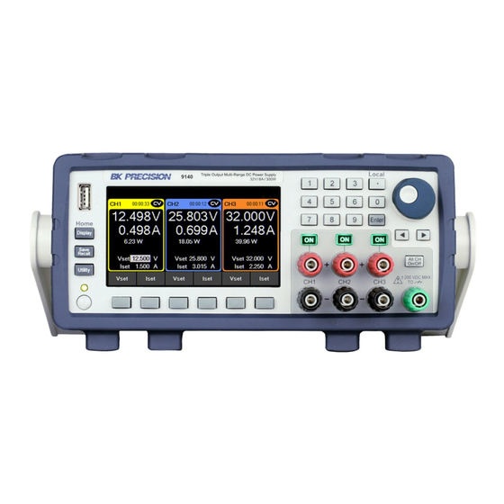
9141: 60 V / 4 A / 300 W Figure 1.1 Front View The 9140 Series triple output multi-range DC power supplies combine industry-leading power density and performance with an extensive set of features in a compact 2U form factor. -
Page 10: Features
213 mm (8.4 in) x 88.2 mm (3.47 in) x 330 mm (13 in) (W x H x D). Figure 1.2 Dimensions 1.5 Rackmount Installation The 9140 Series is compatible with the optional 19-inch rackmount kit model RK2US. The RK2US installation intructions can be downloaded from bkprecision.com 1.6 Front Panel... -
Page 11: Display
Introduction Item Description Main Display Keypad Triple Channel Output Terminals Rotary Knob Main function keys USB host port Power button Soft Menu Keys 1.7 Display Item Description Indicates output is off Indicates constant voltage mode Indicates constant current mode Tracking mode enabled Indicates remote mode Keyboard lock enabled Indicates data logging is enabled... -
Page 12: Getting Started
Getting Started Before connecting and powering up the instrument, please review and go through the instructions in this chapter. 2.1 Input Power and Fuse Requirements The supply has a universal AC input that accepts line voltage input within: Voltage: 100 - 240 VAC (+/- 10 %) Frequency: 50/60 Hz Input Power: 500 VA MAX. -
Page 13: Check Or Replace Fuse
Getting Started 2.3 Check or Replace Fuse For safety, no power should be applied to the instrument while changing line voltage operation. Disconnect all cables connected to the instrument before proceeding. Check and/or Change Fuse • Locate the fuse box next to the AC input connector in the rear panel. See •... -
Page 14: Preliminary Check
Figure 2.2 Wire Gauge Rating Output Isolation The output terminals of the 9140 Series are isolated from earth ground. An earth ground terminal is provided on the front panel for convenience. Any output terminal may be grounded. However, output terminals must not exceed ±200 VDC. -
Page 15: Self Test Errors
Getting Started After Power on, during the self-test, the following should be displayed: Figure 2.3 Scan System After the system scan is complete the LCD will display as shown in Figure Figure 2.4 Scan complete Note: The initial power on state is based on the settings in Power-ON 2.6 Self test Errors The following errors will be displayed if the self-test did not complete successfully:... -
Page 16: Basic Front Panel Operation
Basic Front Panel Operation At power-on, the power supply will automatically enter the front-panel operation mode and the instrument can be con- trolled via the front panel keys and knob. 3.1 Keys 3.1.1 Main Keys There are three main keys: Opens the main menu bar. -
Page 17: Numeric Keys
Basic Front Panel Operation 3.1.3 Numeric Keys The numeric keys allow the configuration of various parameters. Using the numeric keys provides a fast and precise input. The key can be found with the numeric keys. Pressing enter will assign the selected value to the desired parameter. -
Page 18: Display
Basic Front Panel Operation 3.2 Display These power supplies have three main display modes: three channel display, single channel display, and live output monitoring display. Press the button to cycle between the different display modes or to return home when viewing any other menu. - Page 19 Basic Front Panel Operation Single Channel Display Provides information of the outputs’: Allows configuration of: • State • Vset • Run time • Iset • Voltage • Vmax/Vmin • Current • OVP/OCP • Power • OnDelay/OffDelay • Vmax/Vmin • OVP/OCP •...
- Page 20 Basic Front Panel Operation Live Output Monitoring The live output monitoring display shows metered output voltage and current over time. It is always active and will continuously plot and overwrite the oldest value when the display graph is full. Figure 3.5 Live Output Monitoring Display The Live output display can be configured by setting the: Voltage, Current, and Time Scale.
-
Page 21: Check Model And Firmware Version
Basic Front Panel Operation Voltage Offset A voltage offset can be added to each output. The offset can be set from 0 V up to 60.6 V on the 9141 and 0 V up to 32.2 V on the 9140. 1. -
Page 22: Output Configuration
Output Configuration 4.1 Protection Settings 4.1.1 Over Voltage Protection (OVP) Over voltage protection is always enabled, however the user can set the OVP voltage limits. 1. Press the button then use the soft keys to select Output config > Protection settings 2. -
Page 23: Vmax/Vmin
Output Configuration 4.1.4 Vmax/Vmin Configure the maximum or minimum voltage value the user can set from the protection settings. 1. Press the button then use the soft keys to select Output config > Protection settings 2. Use the soft keys to select a channel to adjust. 3. -
Page 24: Output Timer
Output Configuration DO NOT at any time disconnect the wires from the S+ and S- terminals to the DUT while output is enabled (ON). Doing so may damage the power supply and cause unstable output. Remote sense is disabled by default, see the following steps to enable remote sense: 1. -
Page 25: On/Off Delay
Output Configuration 4.2.5 On/Off Delay A channel on or off delay in seconds can be applied to any channel. These delays can be set from 0.001 s to 3600.0 s. 1. Press the button then use the soft key to select Output config > Output Settings. 2. - Page 26 Output Configuration In Normal mode the main page will display the three outputs. Toggles through CH1, CH2, CH3, and live output monitoring display. Figure 4.4 Normal Mode Main Page Single CH displays more information about the output, and allows configuration of more parameters. Figure 4.5 Single Channel...
-
Page 27: Series Mode
Output Configuration 4.3.2 Series Mode Set operation mode to Series. Series mode changes the UI to accurately represent the possible outputs configurations. Series mode does not internally wire the outputs. The outputs must be connected externally to increase the available voltage range. - Page 28 Output Configuration CH1 + CH2 Operation mode will be set to Series 1 + 2. Changing operation mode will undo previous coupling configuration. Press the button then use the soft key to select Output Config > Op. Mode/Coupling > Operation Mode > Series > CH1 + CH2. Figure 4.6 Series 1+2 In Series CH1 + 2 the main page will display the output of the combined outputs, as well as the output of the individual CH3.
- Page 29 Output Configuration Single CH displays more information about the output, and allows configuration of more parameters. The voltage configurations will now range from 0 v to 64 V for model 9140 and 0 V to 120 V for model 9141. Figure 4.8 Series CH1+2 Single Channel Display Protection Setting menu will also adjust the configurable values.
- Page 30 Output Configuration Series All Operation mode will be set to Series All. Coupling will not be available in Series All mode. Press the button then use the soft key to select Output Config > Op. Mode/Coupling > Operation Mode > Series > Series All. Figure 4.10 Series All In Series All mode will only toggle between the Series All display and live output monitoring.
- Page 31 Output Configuration Parallel Mode Set operation mode to Parallel. Parallel Mode does not internally wire the outputs. The outputs must be connected externally to increase the available current range. Parallel Mode changes the UI to accurately represent the possible output configurations. Press the button then use the soft key to select Output Config >...
- Page 32 Output Configuration CH1 + CH2 Operation mode will be set to Parallel 1 + 2. Selecting an operation mode will undo previous coupling configuration. Press the button then use the soft key to select Output Config > Op. Mode/Coupling > Operation Mode >...
- Page 33 Output Configuration The Single CH display will adjust to allow current configuration between .030 A to 16 A for model 9140 and .030 A to 8 A for model 9141. Figure 4.14 Parallel CH 1+2 Single Channel Display Protection Setting menu will also adjust the configurable range of each parameter. Figure 4.15 Parallel CH 1+2 Protection Settings...
- Page 34 Output Configuration Parallel All Operation mode will be updated based on selected mode. Coupling is not available. Figure 4.16 Parallel All Operation Mode In Parallel All Mode the button will only toggle between the Parallel All display and live output monitoring. Parallel All CH display will adjust to allow value configuration of .045 to 24 A for model 9140 and .045 A to 12 A for model 9141.
- Page 35 Output Configuration Figure 4.18 Parallel All Main Page Tracking Voltage levels are tracked on either CH1+2 or All Channels. Press the button then use the soft key to select Output Config > Op. Mode/Coupling > Operation Mode > Tracking. Tracking mode allows real time voltage tracking across all channels or between CH1 and CH2. When tracking mode is enabled, list mode will still operate independently on the channel that has list enabled.
- Page 36 Output Configuration Coupling Enable or disable the output coupling between multiple output channels, by using the soft keys to toggle individual channel coupling On or Off. Press the button then use the soft key to select Output Config > Op. Mode/Coupling If coupling is enabled, will follow the coupling settings.
- Page 37 Output Configuration Output Sequencing Figure 4.21 Sequencing Combine CH Coupling with Output On and Off Delay to toggle the outputs in a set sequence. To configure a sequence: 1. Set voltage and current output of the participating channels. Reference section Setting Voltage and Current.
-
Page 38: List Mode
List Mode The 9140 and 9141 are capable of storing up to 10 programmable lists in the internal memory. Each list can have up to 100 configurable steps. List memory is shareable across all 3 channels, allowing the channels to run the same list or different list simultaneously. If all ten list numbers are taken, a list can also be saved to a USB. - Page 39 List Mode Pace: Set the pace in which steps are executed. a. Dwell: The next step outputs once the dwell time elapsed. b. Trigger: Afte the dwell time elapsed, wait for a trigger before outputting the next step. Trigger Source Set the trigger source.
-
Page 40: Edit List
List Mode 5.2 Edit List Press the button then use the soft key to select List Setup > Edit List. Use the softkeys to set the following parameters. 5.2.1 Load/Save List Save to USB Save the selected list program to a USB. Use the rotary knob to navigate through the file paths of the USB. -
Page 41: List Number
List Mode Load from USB Load a previously saved list from a USB to selected List Number. Use the rotary knob to navigate through the file paths of the USB. Use the button to expand folders. Once the desired location has been found select Load by pressing the softkey furthest to the left. Figure 5.4 Load from USB Note: The list must be saved/overwritten at the selected list number location before it is able to be as-... -
Page 42: Repeat
List Mode 5.2.3 Repeat To repeat a list, set Repeat using the numeric keypad or rotary knob and press 5.2.4 Steps Add, delete, clear all, or edit steps. Add Step Use the softkeys to add a step to the list. The step added will be a duplication of the step selected before pressing Add Step. - Page 43 List Mode Edit Step Use the rotary knob to navigate the steps available.(select a row) To edit parameters of the step, use the keys.(selects a column) See figure for the parameter each row edits. Press to toggle enable/disable BOST and/or EOST. Figure 5.6 List Configuration Step Parameters Voltage...
-
Page 44: List Run
List Mode 5.3 List Run List allows a sequence of outputs with up to 100 configurable steps. With sharable memory across all three channels, a list can run simultaneously on various channels. This allows for a list to be compatible in normal, parallel or series mode. Before running a list its parameters must be configured. - Page 45 List Mode 4. Select List start to start the list. – Once the list begins List Start will change to Abort List – The interaction with the list will vary depending on the chosen Pace. See 5. Select List Abort to end the list before all steps elapse. If the all steps elapse the list will end and the output will be set to chosen After List parameter.
-
Page 46: Data Logger
Data Logger The data logger can record the output voltage, current, and error codes of all three channels. Log data can be configured to record either Voltage only, Current only, or both. Connect a USB flash drive to the front panel USB port. Max. Recording time will vary based on the flash drive size and the amount of the data being logged. -
Page 47: Parameters
Data Logger 6.2 Parameters 6.2.1 Sampling Interval Press the button then use the soft key to select Data logger > Sampling Interval. Use the numeric keypad or rotary motor to select the sampling interval. Press to assign the selected value. (.2s to 300s) 6.2.2 File Path Press the... -
Page 48: Log Data
Data Logger 6.2.4 Log Data Press the button then use the soft key to select Data logger > Next Pg. > Log Data. Select data to be logged. – All: Record both voltage and current output of all channels. – Voltage: Record the voltage output of all channels. –... -
Page 49: Status Code
Data Logger 6.2.5 Status Code Press the button then use the soft key to select Data logger > Status Code. Toggle to enable/disable status code. Enabled Status Code will record all codes reported. See for an example. In figure the code 0x0001 is returned. This indicates OVP has been triggered. Table defines each code. -
Page 50: Utilities Menu
Utilities Menu Configure the settings in the following menus: • User Settings • Remote Interface • I/O Configuration • Test/Admin • Error Log • Help 7.1 User Settings Press the button then use the soft key to select Utilities > User Settings. The system’s settings can be configured here. -
Page 51: Time
On Screen Help see section 7.2 Remote Interface The 9140 series supports remote communication on up to three interfaces: USB, LAN, and GPIB (optional). While in remote mode the screen displays “RMT” in the upper right corner. Switching to remote mode does not impact the supply’s output parameters. -
Page 52: Usb Settings
Utilities > I/O Config > USB Settings. The USB device port is located in the rear-panel. See The 9140 series are both USBTMC and USB VCP compliant. In the USB Settings menu use the soft keys to select either: –... -
Page 53: Lan
Utilities Menu 7.2.2 LAN To configure the LAN Settings Press the button then use the soft key to select Utilities > I/O Config > LAN Settings. The following settings are available in LAN Settings: • IP Mode • IP Address •... - Page 54 Utilities Menu Subnet Mask Subnet Mask divides the IP address into network address and host address. To set Subnet Mask: Press the button then use the soft key to select Utilities > I/O Config > LAN Settings > Subnet Mask. Use the numeric keypad to enter the subnet mask.
- Page 55 Utilities Menu LAN Reset LAN Reset resets all LAN settings and webpage passwords. To reset LAN : Press the button then use the soft key to select Utilities > I/O Config > LAN Settings > LAN Reset . Before resetting a warning will display informing both LAN settings and webpages passwords will be reset. Figure 7.4 Reset Select Yes to finalize the reset.
- Page 56 Utilities Menu Restore Default Restore Default will set all LAN settings to their factory defaults. To restore factory defaults: Press the button then use the soft key to select Utilities > I/O Config > LAN Settings > Restore Default . Before restoring LAN settings to default the following warning will display.
- Page 57 Utilities Menu LAN Status LAN Status provides an overview of the LAN settings. To view the LAN status: Press the button then use the soft key to select Utilities > I/O Config > LAN Status . Figure 7.6 LAN Status...
-
Page 58: Gpib (Optional)
Utilities Menu 7.3 GPIB (optional) In GPIB the GPIB address can be changed from 01 to 30. To change the GPIB address: Press the button then use the soft key to select Utilities > I/O Config > GPIB. Figure 7.7 GPIB Address Use the numeric keypad to enter the new address, then press the key. -
Page 59: Digital I/O
Utilities Menu 7.4 Digital I/O To enter the Digital I/O menu: Press the button then use the soft key to select Utilities > I/O Config > Digital I/O. Select the function and polarity of pins: 1, 2, and 3. • Pin Functions •... -
Page 60: Polarity
Utilities Menu Digital In Toggle to select In/Out digital function. Digital In: Receive a signal from external device. Digital Out: Send a signal to external device. The input voltage range for digital I/O pins is 0 V to 5 V. To prevent damage to the instrument, do not exceed 5 V or supply a negative voltage to the digital I/O pins. -
Page 61: Inhibit Mode
Utilities Menu 7.4.1 Inhibit Mode Receive an external input signal that controls the output state of all channels. Default: To set Inhibit Mode: 1. Assign the inhibit In function to pin 3 by: Press the button then use the soft key to select Utilities > I/O Config > Digital I/O > Pin 3 > Inhibit 2. -
Page 62: Test/Admin
Utilities Menu 7.5 Test/Admin 7.5.1 Self Test Run a Module test. Press the button then use the soft key to select Utilities > Test/Admin > Self-Test > Start. Figure 7.9 Self Test Complete 7.5.2 Security The Security Settings are locked and can be accessed by entering the default code 77416699. Figure 7.10 Security Locked Note: The default password can be change in the Change Code menu. - Page 63 Utilities Menu Use the password to gain access to the following settings. • Change Code • Calibrate • Firmware Update • NISPOM • Lock Change Code Changes the security code. Press the button then use the soft key to select Utilities > Test/Admin > Security > Change Code. Calibrate Enter calibration mode.
-
Page 64: Error Log
Utilities Menu 7.6 Error Log View up to 50 previously set error codes. Press the button then use the soft key to select Utilities > Error Log. Figure 7.11 Error Log Errors are placed in the order that they were encountered. 1 being the most recent. The error log displays up to 50 error codes. -
Page 65: Help
Utilities Menu 7.7 Help To enter the Help menu: Press the button then use the soft key to select Utilities > Help. Figure 7.12 Help Menu Use the rotary knob to navigate the help options shown in figure 7.12. To select the Quick help topic press the key or press the Select softkey. -
Page 66: Key Lock
Key Lock Lock all front panel keys including Press the button then use press and hold the soft keys Key Lock for 3 seconds. Figure 8.1 Key Lock If Key Lock Output is enabled, holding Key Lock for 3 seconds locks all front panel keys except See section to enable/disable Key Lock Output. -
Page 67: Save/Recall
Save/Recall Save/Recall the instruments Output Settings and Power-On Settings. 9.1 Save the Output Settings Save to Internal Memory Save the instrument’s output settings to the internal memory. A total of 10 (0 to 9) output settings can be saved. To save the output settings : Press the button then use the soft keys to select Save >... -
Page 68: Recall The Instrument's Settings
Save/Recall Figure 9.2 Save to USB 9.2 Recall the Instrument’s Settings Recall previously saved output settings from the internal memory. A total of 10 (0 to 9) user settings can be saved. To recall settings : Press the button then use the soft keys to select Recall > Recall from INT. Use the numeric keypad to enter a number from 0 to 9 to recall the output settings stored in that address. -
Page 69: Power-On Settings
Save/Recall Use the rotary knob to navigate through the file paths of the USB. Use the button to expand folders. Once the desired location has been found press Load. The settings will be recalled after a short delay. Figure 9.4 Recall from USB 9.3 Power-On Settings Load previously saved output parameters on power-on. -
Page 70: Screenshot
Save/Recall Default Values and Ranges Set the instrument’s output settings to default. Press the button then use the soft keys to select Set to Default. 9140 9141 Parameter Unit Default Default VSET 32.32 60.6 ISET 8.08 .015 4.04 .015 Vmax 32.32 32.32 60.6... -
Page 71: Calibration Adjustment Procedure
Calibration Adjustment Procedure Calibration Interval The recommended calibration interval for the 9140 series is one year. To enter the Calibration Menu: Press the button, then use the soft key to select Utilities > Test/Admin > Security > Calibrate. In the Calibration Menu use the softkeys to select a parameter from the menu to calibrate. -
Page 72: Voltage Calibration Adjustment
Calibration Adjustment Procedure 10.1 Voltage Calibration Adjustment For the voltage calibration procedure a precise DMM will be needed. To adjust the voltage calibration: 1. Enter the Calibration Menu • Press the button, then use the soft key to select Utilities > Test/Admin > Security. Use the numeric keypad to enter security code. -
Page 73: Current Calibration Adjustment
Calibration Adjustment Procedure 10.2 Current Calibration Adjustment For the current calibration procedure a precise DMM will be needed. To adjust the current calibration: 1. Enter the Calibration Menu • Press the button, then use the soft key to select Utilities > Test/Admin > Security. Use the numeric keypad to enter security code. -
Page 74: Ovp Calibration Adjustment
Calibration Adjustment Procedure 10.3 OVP Calibration Adjustment For the over voltage protection calibration the instrument’s voltage must be calibrated. To adjust the OVP calibration: 1. Enter the Calibration Menu • Press the button, then use the soft key to select Utilities > Test/Admin > Security. Use the numeric keypad to enter security code. -
Page 75: Ocp Calibration Adjustment
Calibration Adjustment Procedure 10.4 OCP Calibration Adjustment For the over current protection calibration the instrument’s current must be calibrated. To adjust the OCP calibration: 1. Enter the Calibration Menu • Press the button, then use the soft key to select Utilities > Test/Admin > Security. Use the numeric keypad to enter security code. -
Page 76: Rtc Calibration Adjustment
Calibration Adjustment Procedure 10.5 RTC Calibration Adjustment To adjust the Real-Time Clock(RTC) calibration: 1. Enter the Calibration Menu • Press the button, then use the soft key to select Utilities > Test/Admin > Security. Use the numeric keypad to enter security code. See the subsection Security. Press the button to enter the security menu. -
Page 77: Performance Verification
Performance Verification Performance verification ensures the instrument will meet specifications listed in the datasheet. Load regulation can be tested for both the front and rear outputs. Note: All specifications apply to the unit after a temperature stabilization time of 15 minutes over an am- bient temperature range of 23 °C ±... - Page 78 Performance Verification 5. Set the electronic load settings to the stated values in table 11.1. 6. Enable the channel output. 7. Enable the electronic load. Monitor the power supply to ensure it remains in CV mode.If the power supply switches to CC slightly lower the current on the electronic load until the power supply return to CV mode.
- Page 79 Performance Verification 7. Enable the electronic load. Monitor the power supply to ensure it remains in CV mode.If the power supply switches to CC slightly lower the current on the electronic load until the power supply return to CV mode. 8.
- Page 80 20 ms Full load 10 ms 20 ms Fall Time No load 250 ms 250 ms Ordering Information Transient Response 9140 Series Power Supplies Time 0.5 ms Protection Model Description 9140 32 V / 8 A, 300 W Range 35.2 V...
-
Page 81: Service Information
Service Information Warranty Service: Please go to the support and service section on our website at bkprecision.com to obtain an RMA #. Return the product in the original packaging with proof of purchase to the address below. Clearly state on the RMA the performance problem and return any leads, probes, connectors and accessories that you are using with the device. -
Page 82: Limited Three-Year Warranty
LIMITED THREE-YEAR WARRANTY B&K Precision Corp. warrants to the original purchaser that its products and the component parts thereof, will be free from defects in workmanship and materials for a period of three years from date of purchase. B&K Precision Corp. will, without charge, repair or replace, at its option, defective product or component parts. Returned product must be accompanied by proof of the purchase date in the form of a sales receipt.
Need help?
Do you have a question about the 9140 Series and is the answer not in the manual?
Questions and answers