
Related Manuals for BK Precision 1698


Summary of Contents for BK Precision 1698
- Page 1 INSTRUCTION MANUAL Model 1696/1697/1698 Modelo 1696 / 1697 / 1698 MANUAL DE INSTRUCCIONES LABORATORY GRADE SWITCHING MODE PROGRAMMABLE DC POWER SUPPLIES with PC INTERFACE...
-
Page 2: Table Of Contents
TABLE OF CONTENTS 1. IMPORTANT SAFETY INSTRUCTIONS & PRECAUTIONS FOR USE .............. 3 2. SPECIFICATIONS ............................4 3. INTRODUCTION .............................. 5 4. CONTROLS & INDICATORS ........................... 6 5. GENERAL OPERATING PRINCIPLE ......................8 6. OPERATING INSTRUCTIONS ......................... 9 6.1 SETTING OF OPERATION MODE ......................9 6.2. -
Page 3: Important Safety Instructions & Precautions For Use
In the event this problem persists, the unit must be investigated by your agent. Only use the supplied software and optional accessories with this unit. Refer all servicing to manufacturer. Warning! The maximum output voltage for Model 1698 is up to 60Vdc. It may be hazardous to touch metal part of the terminals. -
Page 4: Specifications
2. Technical Specifications of models 1696, 1697, 1698 Specifications 1696 1697 1698 Output Voltage 1-20VDC 10-5A -40VDC 1-60VDC Output Current 0-10A 0-5A 0-3.3A Ripple & Noise (P-P) 25mV 25mV 25mV Load Regulation 0.5% + 200mV 0.5% + 200mV 0.5% + 200mV... -
Page 5: Introduction
3. INTRODUCTION This series of laboratory grade, switching mode, programmable power supplies are ideal for repetitive test routines in R&D, Production, Product Evaluation and various applications. Information appearing on the large back-lit LCD makes the panel controls simple and easy to use in spite of its sophisticated features. Because of the MCU (Micro-Controller Unit) and the related software, user re-calibration without opening the case is an added bonus. -
Page 6: Controls & Indicators
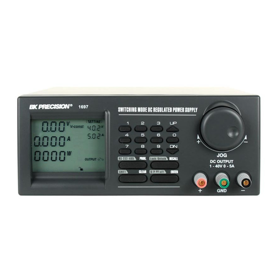
4. CONTROLS AND INDICATORS FRONT PANEL JOG DIAL UP & DOWN KEY DUAL FUNCTION CONTROL KEYS BLACK COLOR NEGATIVE POLARITY OUTPUT TERMINAL RED COLOR POSITIVE POLARITY OUTPUT TERMINAL GREEN COLOR GROUND TERMINAL (connected to chassis) -
Page 7: Controls And Indicators
4. CONTROLS AND INDICATORS BACK PANEL POWER SWITCH AC 100 - 240VAC POWER SOCKET WITH INPUT POWER FUSE RS-232 PORT RS-485 PORT... -
Page 8: General Operating Principle
5. GENERAL OPERATION PRINCIPLE There are four operation methods for this unit: • Manual Operation • Presets • Timed Program • PC Interface Mode. • The large Liquid Crystal Display will guide you through the various operations/procedures interactively once you understand the operation principle. There are four Dual Function Control Keys for various operation modes and input states of the unit. -
Page 9: Operating Instructions
6. OPERATING INSTRUCTIONS 6.1 Setting of Operation Modes Output On/Off Mode Press SHIFT key. The display will show Sh:Ft. Press (O/P On/Off) key within 3 seconds. Watch for the appearing On/Off symbol in the display to confirm your setting, otherwise repeat the above procedure. Lock/Unlock the Keypad and Jog Dial Press SHIFT key. - Page 10 OPERATING INSTRUCTIONS Precaution Reset back to the maximum rated voltage of the unit is recommended to avoid false fault report of the unit Press SHIFT and follow by 0 key. The display will show and the present upper voltage limit. Input your desired voltage followed by ENTER to confirm.
- Page 11 OPERATING INSTRUCTIONS Showing output terminals in ON/OFF state. Showing keypad & Jog dial are in Locked (de-activated) or Unlock (activated) state. Unit is ready for or has already been linked up with computer. OUTPUT ENABLE/DISABLE AT POWER UP Press the SHIFT then the UP key. This will enable the output at power up.
- Page 12 STANDARD OPERATION SYMBOLS V- const Constant Voltage mode showing set voltage. V- set This only appears voltage level is ready for setting. I-set This only appears current level is ready for setting. I-const This only appears when unit is in (CC) constant current mode. They show the actual Volts, Amperes and Watts at the output terminals.
-
Page 13: Manual Operation Mode
6.2 Manual Operation Mode In the Manual Operation Mode, once the voltage and current levels have been set, the unit wi11 keep these settings even after unit has been switched off until further reset. There are 3 ways to input a setting: 1. -
Page 14: Using The Preset Feature
7. USING THE PRESET FEATURES PRESET PROGRAM SYMBOLS Program Unit is ready for inputting of a Preset Program Number (19). Recall Unit is ready for recalling a Preset Program Number. The unit can store nine preset voltage and current settings. Once programmed, these settings will be retained even when the unit is switched off. -
Page 15: Operating The Timed Program
Selecting Presets 1. Press the RECALL key The display will show Recall_ 2. Press the number key (1-9). The display will show the chosen Preset Number, its voltage and current level. 3. Press ENTER to activate .The unit will resume the chosen reset values. If during any of the above procedures, you fail to input a setting within 10 seconds, the unit will cancel the procedure and resume the previous settings. -
Page 16: Running The Timed Program
Note: A. Once the subprograms are filled, the unit will return to manual operation mode. Any subprogram with zero time period will become the Terminating Subprogram. For example, if you set the subprogram 7 with zero time period, all the subprograms after 7 (i.e. 8, 9, 10-19) become non-existent. The timed program will only cycle from subprogram 0 (STEP) to subprogram 6. - Page 17 TIMED PROGRAM SYMBOLS 1. Inputting Subprograms...
- Page 18 2. Symbols Running in a Timed Program Cycle Unit is ready for the recheck of all subprogram settings.
-
Page 19: Maintenance
8. MAINTENANCE 8.1 RECALIBRATION Introduction This in-case recalibration is to reduce the difference between the Set values and the displayed values on the LCD Display. You only use the recalibration when the difference is greater than 0.1V for voltage or -0.01A / +0.02A for current. The whole recalibration for voltages and current takes less than 15 minutes. It is performed by a proprietary software using regression algorithm. -
Page 20: Trouble Shooting
8.2 TROUBLE SHOOTING 1. Keypad and Dial do not work. Check key lock symbol for lock state, unlock unit by pressing SHIFT then Lock/Unlock key, otherwise switch the unit off and then back on to see if the problem persists. 2. -
Page 21: Pc Interface Control User Manual
9. PC INTERFACE CONTROL USER MANUAL 9.1 Introduction We integrate the micro-controller technology and our proprietary software with switching mode power technology to make this unit user friendly, time saving and reliable power supply. In PC interface mode: 1. With our proprietary software one PC can perform remote access/control and output data logging for one programmable power supply with RS-232 or up to 31 programmable power supplies using RS-485 interface. -
Page 22: Rs-232 Interface Operation
3. Finally a software icon is created in the program menu. 9.3 Operation Instruction for RS-232 Interface 1. Ensure that the PC is off; connect RS-232 to serial COM port of your PC and the power supply. 2. On your power supply, press the [SHIFT] key, and then quickly press [RS-232/485] key and select RS-232 (pressing the [RS-232/485] will toggle between RS-232 and RS-485) followed by the [ENTER] key. - Page 23 D. Check to make sure that the power supply is turned on. Setting Once you bring up the software you can your desired sample time from 1 second up from the drop menu. Data log Sampling Time You can set your output voltage upper limit value to further safeguard your low voltage applications.
-
Page 24: Rs-485 Interface Operation
Log Name Click cursor on "Untitle", type in a name for your log. Note how the ###(5) icon changes to solid color. Log Description You can type in a detailed description of your log. ##### Save Log This function (and the icon) becomes effective when a Log Name is entered to replace the "Untitle". By clicking on it will save the current data onto the PC. - Page 25 Print Log in xls format. P.22 THE DATA LOG WINDOW DISPLAY...
- Page 26 THE TIME FRAME CONCEPT OF DATA LOG The data logging function starts when the software begins to run. When T Min is set to zero seconds, it means the unit is on real time and the length of time lapsed is on the left hand side of the Time Minimum. T Len is the length of time lapsed strafing from the Time Minimum.
-
Page 27: General Information
GENERAL INFORMATION serial no S2405000 Please refer to (Fig. 3) for the following description. 10. Power Supply Description: You may click on and assign an identification number for your power supply in use. Actually this feature is used mainly when you have multiple power supplies in use via the RS-485. 11. - Page 28 Internal Timed Program The PC interface remote mode really eliminates the tedious process in keying in groups of entries on the power supply. Because all the data are displayed together in the monitor, the possibility of wrong entry is greatly reduced. Data of different groups can be classified, store, exported and retrieved for use at any time. Retrieved data will be in red color if they exceed the present pre-set limits of voltage in upper voltage level or current limiting value.
-
Page 29: Configuration Of Each Power Supply
Internal Preset Memory The operation principle is the same as Internal Timed Program To activate the selected preset, click on the box of the [Select] column then click Run. If retrieved or entered data exceed present Upper or Lower limit setting of voltage/current/time, the data becomes red in color. 9.4 Operation Instruction for RS-485 Interface This interface operation is provided for remote access/control up to 31 power supplies. - Page 30 On your power supplies, press [SHIFT] key, then quickly press [RS-232/485] key and select RS-485. A 3-digit number will be displayed. This number is the address assigned to the power supply and will be used in the software. Using the Key Pad to key in the address to assign for each power supply. The range is 001-031 and each of the power supplies requires a unique address.
-
Page 31: Configuration Of Multi Windows Analysis
9.4.2 Configuration of Multi Windows Analysis In the tool bar, click on Supply Connect, then click on Multi in the drop menu. A multi-window (Fig. 6) will appear. Click on the icon (circled as below) a Multi Power Supply Connect Set Up (Fig. 7) (FIG. - Page 32 4. Click on AutoScan Connect, the window will show the connected power supply indicated with “Y”. (FIG. 7) 5. Click on the box along the visible column to set the desired power supply to be visible in Multiple Data log window. 6.
- Page 33 8. Remarks: Multi Alleyway Display one click and it will display the Data Log and output data of all the power supplies. It will activate the icon 2, 3 & 4. Show Digital and Log one click and it will show both the data log of all connected power supplies.
- Page 34 (FIG. 9) You can click on the data log to select the power supply, the data log will highlight in blue and the address bar in the left bottom window will show the selected power supply. Show Digital - one click and will show the digital readings of all the connected power supplies. Show Log - one click and it wi11 show the data log of all the connected power supplies.
- Page 35 Save Log: Click on it and save log window (Fig. 13) will appear. Click on the box along the Save column to choose the desired power supply data log to save. Type in the table name. Click save will save the current data onto the PC. To retrieve data, go to the drop menu at Log (13).
- Page 36 10. Delete Log It will delete log data in PC 11. Export to a file log of xls type Click on this icon to export the collected data in Data Log in xls format to your PC. 12. Open File Log of xls type (FIG.
-
Page 37: Service Information
Service Information Warranty Service: Please return the product in the original packaging with proof of purchase to the address below. Clearly state in writing the performance problem and return any leads, probes, connectors and accessories that you are using with the device. Non-Warranty Service: Return the product in the original packaging to the address below. -
Page 38: Warranty Information
Limited Two-Year Warranty B&K Precision Corp. warrants to the original purchaser that its products and the component parts thereof will be free from defects in workmanship and materials for a period of two years from date of purchase. B&K Precision Corp. will, without charge, repair or replace, at its option, defective product or component parts. Returned product must be accompanied by proof of the purchase date in the form of a sales receipt. - Page 39 22820 Savi Ranch Parkway Yorba Linda, CA 92887 www.bkprecision.com © 2006 B&K Precision Corp. Printed in PN # 481-522-9-001 v.062111...
- Page 40 Command Sets BK models 1696/1697/1698 BLUE – Input Command RED – Return Data from Power Supply PS = Power Supply Command Code Description Disable front panel keypad SESS <address> <CR> [OK] [CR] and make PS to Remote Mode Enable front panel keypad ENDS <address>...
- Page 41 GETM <address> <CR> Memory 1 Voltage [???] Current [???] [CR] Get All Preset Memory Memory 2 Voltage [???] Current [???] [CR] ....Memory 9 Values from PS Voltage [???] Current [???] [CR] [OK] [CR] Get Memory from Specific GETM <address>...
- Page 42 Set Current Level CURR <address> current {001-XXX} <CR> [OK] [CR] Set Upper Voltage Limit of SOVP <address> voltage {010-XXX} <CR> [OK] [CR] Disable Output of PS SOUT <address> 0 <CR> [OK] [CR] SOUT <address> 1 <CR> [OK] [CR] Enable Output of PS Set Voltage and Current PROM <address>...
Need help?
Do you have a question about the 1698 and is the answer not in the manual?
Questions and answers