
Related Manuals for BK Precision 9129B


Summary of Contents for BK Precision 9129B
- Page 1 Model 9129B Triple Output Programmable DC Power Supply USER MANUAL GlobalTestSupply www. .com Find Quality Products Online at: sales@GlobalTestSupply.com...
- Page 2 Safety Summary The following safety precautions apply to both operating and maintenance personnel and must be followed during all phases of operation, service, and repair of this instrument. Before applying power to this instrument: • Read and understand the safety and operational information in this manual. •...
- Page 3 is specified in this manual for this instrument. You must ensure that each accessory you use with this instrument has a category rating equal to or higher than the instrument's category rating to maintain the instrument's category rating. Failure to do so will lower the category rating of the measuring system. Electrical Power This instrument is intended to be powered from a CATEGORY II mains power environment.
- Page 4 • In environments where there is a danger of any liquid being spilled on the instrument or where any liquid can condense on the instrument. • In air temperatures exceeding the specified operating temperatures. • In atmospheric pressures outside the specified altitude limits or where the surrounding gas is not air.
- Page 5 Instrument covers must not be removed by operating personnel. Component replacement and internal adjustments must be made by qualified service-trained maintenance personnel who are aware of the hazards involved when the instrument's covers and shields are removed. Under certain conditions, even with the power cord removed, dangerous voltages may exist when the covers are removed.
- Page 6 cannot verify the fan is operating (note some fans may have intermittent duty cycles). Do not insert any object into the fan's inlet or outlet. Use correctly sized wires To connect a load to the power supply, use a wire diameter large enough to handle the maximum continuous output short-circuit current of the power supply without the wire overheating.
-
Page 7: Compliance Statements
Compliance Statements Disposal of Old Electrical & Electronic Equipment (Applicable in the European Union and other European countries with separate collection systems) This product is subject to Directive 2002/96/EC of the European Parliament and the Council of the European Union on waste electrical and electronic equipment (WEEE), and in jurisdictions adopting that Directive, is marked as being put on the market after August 13, 2005, and should not be disposed of as unsorted municipal waste. - Page 8 CE Declaration of Conformity This instrument meets the requirements of 2006/95/EC Low Voltage Directive and 2004/108/EC Electromagnetic Compatibility Directive with the following standards. Low Voltage Directive EN61010-1: 2001 EMC Directive EN 61000-3-2: 2006 EN 61000-3-3: 1995+A1: 2001+A2: 2005 EN 61000-4-2 / -3 / -4 / -5 / -6 / -11 EN 61326-1: 2006 GlobalTestSupply www.
-
Page 9: Safety Symbols
Safety Symbols Refer to the user manual for warning information to avoid hazard or personal injury and prevent damage to instrument. Electric Shock hazard On (Supply). This is the AC mains connect/disconnect switch on the front of the instrument. Off (Supply). This is the AC mains connect/disconnect switch on the front of the instrument. -
Page 10: Table Of Contents
Table of Contents Safety Summary ....................i Compliance Statements ......................vi Safety Symbols .......................... viii General Information ..................1 Product Overview ......................1 Package Contents ......................2 Product Dimensions ......................2 Rackmount Installation..................... 3 Front Panel Overview ....................... 4 Rear Panel Overview ......................5 Keypad Overview ...................... - Page 11 Memory Group ........................17 Combined Series and Parallel Modes ..................17 Tracking Mode ........................20 Limit Voltage Protection (LVP) ..................21 Setting Voltage and Current ................... 22 Save and Recall ....................... 22 Select Memory Group ......................23 Save Settings ......................... 23 Recall Settings ........................
-
Page 12: General Information
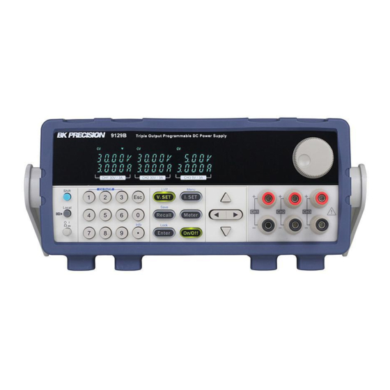
1 General Information 1.1 Product Overview The 9129B is a fully Programmable Triple Output DC Power Supply delivering 0-30V/ 0-3A on channels 1 and 2 and 0-5V/0-3A on channel 3. Each output can be adjusted independently and they can be connected (CH1 and CH2) in series or parallel to produce higher voltages or currents. -
Page 13: Package Contents
B&K Precision. 1.3 Product Dimensions The 9129B power supply dimensions are approximately 214.5 mm (8.44 in) x 88.2 mm (3.47 in) x 376.6 mm (14.8268 in) (W x H x D). Note: All dimensions in the figures below are measured in millimeters (mm). -
Page 14: Rackmount Installation
1.4 Rackmount Installation The instrument can be installed in a standard 19-inch rack using the optional IT-E151 rackmount kit. Below is an image of a 9200 Series model installed with the IT-E151 rackmount kit. Note: Remove the carrying handle and the two plastic ears before mounting the instrument. To remove the handle, grasp the handle by its sides, pull outwards, and rotate it until the arrow on the handle and the arrow on the plastic ears are in opposite directions. -
Page 15: Front Panel Overview
1.5 Front Panel Overview Figure 1 - Front Panel View Front Panel Description VFD display Shift key Local key Power key Numeric keys Function keys Cursor keys Output terminals Rotary knob GlobalTestSupply www. .com Find Quality Products Online at: sales@GlobalTestSupply.com... -
Page 16: Rear Panel Overview
1.6 Rear Panel Overview Figure 2 - Rear Panel View Rear Panel Description Cooling fan AC power input receptacle & fuse box 110/220 V Power Switch RS-232 (TTL) interface GlobalTestSupply www. .com Find Quality Products Online at: sales@GlobalTestSupply.com... -
Page 17: Keypad Overview
1.7 Keypad Overview Figure 3 - Keypad Keypad Description Shift key Enables access to secondary functions (Labeled in blue) Local key Sets the instrument back to local mode. Power key Power on the instrument. Numeric keypad Enters numeric values for various parameters. Vset /LVP button Configures output voltage or sets the limit voltage protection point for the power supply. -
Page 18: Display Overview
current or navigate through menu items. Esc key Cancel and return to previous menu. 1.8 Display Overview Figure 4 - Display Display Description The power supply is in constant voltage mode The power supply is in constant current mode Indicates shift mode (for access to secondary button functions) Indicates remote mode Indicates the channel currently selected Serial connection mode... -
Page 19: Getting Started
2 Getting Started Before connecting and powering up the instrument, please review and go through the instructions in this chapter. 2.1 Input Power and Fuse Requirements Input Power The supply has a selectable AC input that accepts line voltage input within: Voltage: 110 V (+/- 10 %) or 220 V (+/- 10 %) Frequency: 47 Hz –... -
Page 20: Fuse Requirements
110 VAC or 220 VAC input. Table 1 - Fuse Requirements Model Fuse Specification (110 VAC) Fuse Specification (220 VAC) 9129B T6.3A 250V T3.15A 250V 2.2 Line Voltage Selection The power supplies can be selected to operate with 110 V input or 220 V input. To ensure that... - Page 21 Line Voltage Switch AC power input receptacle Figure 6 - Model 9129B Line Voltage Switch Location Do not connect power to the instrument until the line voltage selection is setup correctly. Applying an incorrect line voltage or configuring the line voltage selection improperly may damage the instrument and void all warranty.
-
Page 22: Output Connections
2.3 Output Connections The main DC output terminal is a binding post terminal on the front panel. Before connecting wires to the output terminals, turn OFF the power supply to avoid damage to the instrument and the device under test (DUT). For safety, load wires must have a wire gauge size large enough to prevent overheating when the power supply operates at maximum short circuit output... -
Page 23: Self-Test Errors
Self-test Errors The following errors will be displayed if self-test did not complete successfully: Error Message on Display Description EEP Err The internal EEPROM is corrupted or damaged. Syst Lost Last system settings within the EEPROM is lost. Chan Lost At least one of the channels did not pass initialization test. - Page 24 3. Using the numeric keypad or the voltage adjust rotary knob, enter a voltage value. The voltage display will now show the value you entered. If entering with numeric keypad, press the button first, then enter the value and press the button.
-
Page 25: Check Model And Firmware Version
, the VFD will display power information; the information includes the following parts: 1. Power Model Display the model of power supply: 9129B 2. Soft Version Software version of power supply: 1.XX Press left or right key or rotate knob, to navigate through power supply information: 3. -
Page 26: Front Panel Operation
3 Front Panel Operation 3.1 MENU All settings and parameters can be configured from the built-in menu system of the power supply. The menu system is divided into the following sections and organized as follows: MENU Set the default state of the outputs to either off or last value used BEEP Enable/disable key sound Select baud rate... -
Page 27: Output Power-On State
Output Power-On State The initial power-on state of the power supply outputs can be configured to either be off or to the last output state. 1. From the MENU, navigate to OUt using the keys. There are two options that can be selected by using the keys or rotary knob. -
Page 28: Memory Group
Select one rate and press the button to select desired baud rate. 3. The cursor will move on to the next option after accepting the command. 4. To exit the menu at any time, press the button. Note: All serial settings must match the settings configured on the PC in order for communication to link successfully. - Page 29 1. From the MENU, navigate to COUP using the keys, the keys or the rotary knob. 2. Select the option OFF and press the button. 3. The power supply will momentarily display OFF SUCC before returning to normal display. Figure 11 - OFF (normal) Wiring Mode Note: Only Channels 1 and 2 can be configured in series or parallel.
- Page 30 3. Power on the unit and verify that the outputs are turned off. The button should not be illuminated. 4. From the MENU, navigate to COUP using the keys, keys or the rotary knob. 5. Select the option SEr and press the button.
-
Page 31: Tracking Mode
Figure 14 - Parallel Wiring Mode, CH1+CH2 3. From the MENU, navigate to COUP using the keys, the keys or the rotary knob. 4. Select the option Par and press the button. The power supply will momentarily display Par SUCC. The VDF will look like below: Figure 15 - Parallel Mode (CH1+CH2) 5. -
Page 32: Limit Voltage Protection (Lvp)
CH2 when the tracking mode is active. 3.2 Limit Voltage Protection (LVP) The 9129B Model power supply provides a Limit Voltage Protection function to protect the power supply when the voltage at the output terminal exceeds the LVP voltage setting or to prevent accidental changes to the output settings that exceeds the DUT (device under test) limit. -
Page 33: Setting Voltage And Current
Note: Avoid exceeding 120% of the rated voltage across the output terminals or the power supply may be damaged. Note: When a specific voltage cannot be set, check the LVP voltage setting to ensure the desired voltage is less than or equal to the LVP value. 3.3 Setting Voltage and Current Follow the steps below to set the output voltage or current. -
Page 34: Select Memory Group
Select Memory Group 1. From the MENU, navigate to the group memory option (Grp) using the keys. There are three options that can be selected by using the keys or rotary knob: Grp1 Grp2 Grp3 2. Select one of the three memory location groups (Grp1, Grp2 or Grp3) and then press button. -
Page 35: Key Lock
3.5 Key Lock The front panel keys can be locked to prevent unwanted changes from the front panel. Follow the steps below to enable/disable key lock. 1. Press the key and then the button. The button will illuminate indicating that the front panel keys are locked. At this point, all keys are disabled except and the buttons. -
Page 36: Protections
Figure 16 - Over Temperature Protection Warning Over Voltage Protection (OVP) The 9129B has over voltage protection function, which may be triggered due to an internal error, wrong operation by the customer, or over voltage at the output terminals. Once the power supply enters the protected OVP state, the user will hear a buzzer sound and the output will be turned off. -
Page 37: Remote Operation
5 Remote Operation Users can program the power supply by using the SCPI (Standard Commands for Programmable Instruments) commands over the TTL remote interface (via USB virtual com with IT-E132B). Note: The RMT indicator will appear on display when the power supply is successfully connected to a PC remotely through any remote interface. -
Page 38: Rs-232 Settings
RS-232 Settings In order for the computer to communicate with the power supply, both must be set to the same RS-232 settings. These communication settings are: Baud rate must be one of 4800, 9600, or 38400 8 data bits One stop bit No parity Refer to the Baud Rate section in the Menu for instructions on how to select a different baud rate. -
Page 39: Remote Commands
6 Remote Commands The instrument supports SCPI commands and some instrument specific commands. These commands enable a computer to remotely communicate and control the instrument over serial using the TTL to USB serial adapter IT-E132B. GlobalTestSupply www. .com Find Quality Products Online at: sales@GlobalTestSupply.com... -
Page 40: Troubleshooting Guide
7 Troubleshooting Guide Below there are some frequently asked questions and answers. Please check if any apply to your power supply before contacting B&K Precision. General Q: I cannot power up the power supply. Check that the power cord is securely connected to the AC input and there is live power from your electrical AC outlet. -
Page 41: Specifications
23 °C ± 5 °C. Specifications are subject to change without notice. Environmental Conditions: This power supply is designed for indoor use and operated with maximum relative humidity of 80%. Model 9129B Output Rating 0-30 V (CH1 & CH2) Voltage 0-5 V (CH3) Current... - Page 42 Series Accuracy Voltage ≤ 0.5% + 30 mV Current ≤ 0.2% + 15 mA Parallel Accuracy Voltage ≤ 0.2% + 30 mV Current ≤ 0.2% + 25 mA General Storage Up to 27 instrument settings Standard USB (virtual com via IT-E132B adapter) Interface AC Input 110/220 VAC (+/- 10 %), 47 Hz - 63 Hz...
-
Page 43: Calibration
9 Calibration We recommend a calibration interval of once per year to ensure that the power supply meets specifications. GlobalTestSupply www. .com Find Quality Products Online at: sales@GlobalTestSupply.com... -
Page 44: Service Information
SERVICE INFORMATION Warranty Service: Please go to the support and service section on our website at to obtain a RMA #. Return the product in the original packaging with proof of purchase to the address below. Clearly state on the RMA the performance problem and return any leads, probes, connectors and accessories that you are using with the device. -
Page 45: Limited Three-Year Warranty
LIMITED THREE-YEAR WARRANTY B&K Precision Corp. warrants to the original purchaser that its products and the component parts thereof, will be free from defects in workmanship and materials for a period of three years from date of purchase. B&K Precision Corp. will, without charge, repair or replace, at its option, defective product or component parts. Returned product must be accompanied by proof of the purchase date in the form of a sales receipt. - Page 46 © 2015 B&K Precision Corp. v090915 GlobalTestSupply www. .com Find Quality Products Online at: sales@GlobalTestSupply.com...
Need help?
Do you have a question about the 9129B and is the answer not in the manual?
Questions and answers