Table of Contents
Advertisement
Quick Links
Advertisement
Table of Contents

Related Manuals for BK Precision MDL4U Series


Summary of Contents for BK Precision MDL4U Series
- Page 2 Safety Summary The following safety precautions apply to both operating and maintenance personnel and must be followed during all phases of operation, service, and repair of this instrument. Before applying power to this instrument: • Read and understand the safety and operational information in this manual. •...
- Page 3 Electrical Power This instrument is intended to be powered from a CATEGORY II mains power environment. The mains power should be 115 V RMS or 230 V RMS. Use only the power cord supplied with the instrument and ensure it is appropriate for your country of use.
- Page 4 Do not operate instrument if damaged If the instrument is damaged, appears to be damaged, or if any liquid, chemical, or other material gets on or inside the instrument, remove the instrument’s power cord, remove the instrument from service, label it as not to be operated, and return the instrument to B&K Precision for repair.
- Page 5 Servicing Do not substitute parts that are not approved by B&K Precision or modify this instrument. Return the instrument to B&K Precision for service and repair to ensure that safety and performance features are maintained. For continued safe use of the instrument •...
- Page 6 Waste Electrical and Electronic Equipment (WEEE) Directive Disposal of Old Electrical & Electronic Equipment (Applicable in the European Union and other European countries with separate collection systems) This product is subject to Directive 2002/96/EC of the European Parliament and the Council of the European Union on waste electrical and electronic equipment (WEEE), and in jurisdictions adopting that Directive, is marked as being put on the market after August 13, 2005, and should not be disposed of as unsorted municipal waste.
-
Page 7: Table Of Contents
Contents Introduction Product Overview Description Features Dimensions Front Panel Rear Panel Protection Functions 1.7.1 Overvoltage Protection (OVP) 1.7.2 Operations to Clear the OVP State 1.7.3 Overcurrent Protection (OCP) 1.7.4 Overpower Protection (OPP) 1.7.5 Overtemperature Protection (OTP) 1.7.6 Reverse Voltage Protection (LRV/RRV) Menu List Installation Inspection... - Page 8 4.6.3 Toggle 4.6.4 Setting Up A/B Transient Operation List Operation 4.7.1 Setting Up List Operation Mode Trigger Operation 4.8.1 Manual Trigger 4.8.2 External Trigger Signal(TTL level) 4.8.3 Hold Trigger 4.8.4 Bust Trigger 4.8.5 Timer Trigger Short Operation 4.10 Input On/Off Operation 4.11 Von Operation 4.12...
-
Page 9: Introduction
Introduction 1.1 Product Overview This section describes the main features and menus of the MDL4U Series DC Electronic Load. The MDL4U Series is comprised of two parts, mainframes and modules. The mainframes mentioned are the MDL4U001 mainframe and the MDL4U002 mainframe extension. Modules in this series include the MDL4U200, MDL4U252, MDL4U302, MDL4U305, MDL4U400, MDL4U505, and MDL4U600. -
Page 10: Features
Introduction * The MDL4U252 and MDL4U302 are dual-channel load modules. The MDL4U252 can allocate up to 250 W to either channel up to 300 W total. (e.g. 250 W/50 W, 150 W/150 W). Similarly, the MDL4U302 can allocate 300 W to either channel up to 600 W total (e.g. -
Page 11: Front Panel
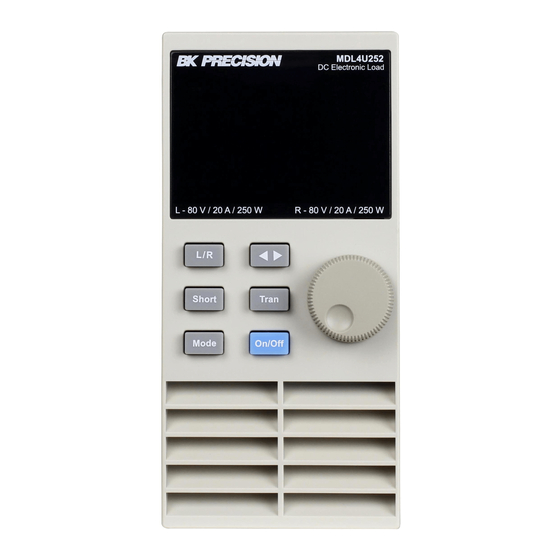
Introduction 1.5 Front Panel Figure 1.2 Front Panel Item Name Description VFD Display Displays electronic load information. Module Panel Keys Controls module functions. Refer to Module section for more details. Rotary Knob Used to change parameters. Mainframe Function Keys Controls each channel’s operating status. Refer to Mainframe for more details. Mainframe Numeric Keypad Used to enter precise values when adjusting parameters. -
Page 12: Rear Panel
Introduction 1.6 Rear Panel Figure 1.3 Rear Panel Item Name Description GPIB Interface Connect a GPIB cable to remotely control the unit Module Input Terminal Load input termianls. Current Monitoring Connect an external voltmeter or oscilloscope to display the input’s current. Remote Sense:Eliminates the effect of voltage drop in the load leads. -
Page 13: Protection Functions
Introduction 1.7 Protection Functions The electronic load has the following protection functions: Overvoltage protection (OVP), overcurrent protection (OCP), overpower protection (OPP), overtemperature protection (OTP), and local and remote reverse voltage protection (LRV/RRV). The mainframe will act appropriately once any of the above protections are active. You can press any button on the front panel to restore the protection function. -
Page 14: Overpower Protection (Opp)
Introduction Operations To Clear the OCP State Check whether the input current is within the electronic load’s rated current or the programmed protection current ranges. If it is outside the range, disconnect the device under test. Then press any key on the front panel or remotely send SCPI command PROTection:CLEar. -
Page 15: Reverse Voltage Protection (Lrv/Rrv)
Introduction 1.7.6 Reverse Voltage Protection (LRV/RRV) This function protects the electronic load in case the input DC voltage lines are connected with the wrong polarity. When a reverse voltage (LRV – local reverse voltage, RRV – remote reverse voltage) connection condition is detected, the input will immediately turn off, the buzzer will alarm the user, and the status register’s reverse voltage (LRV/RRV) and VF bits will be set. - Page 16 Introduction System Menu Press to enter the System menu. MENU INITIALIZE INITIALIZE Resume all configuration to default settings DEFAULT SET POWER ON SET RST (DEFAULT) Set the load’s input state to default at power on SAV0 Set the load’s input state to SAV0 at power on BUZZER SET Set up the buzzer state Enable the function...
- Page 17 Introduction System Menu Cont... GPIB ADDRESS GPIB address setting GPIB ADDRESS SET Set up communication address ETHERNET SET Ethernet settings GATEWAY SET Gateway setting IP SET IP setting MASK SET Mask setting PORT SET Port setting EXIT EXPAND MODULE Module expansion Enable the function OFF (DEFAULT) Disable the function...
- Page 18 Introduction Configuration Menu Cont... ALIMIT POINT Set up software current protection value ALIMIT DELAY Set up software current protection delay PLIMIT POINT Set up software power protection value PLIMIT DELAY Set up software power protection delay ON TIMER STATE Set up LOAD ON timer state ON TIMER SET Set up LOAD ON timer time EXIT...
-
Page 19: Installation
Installation 2.1 Inspection This instrument was carefully inspected before shipment. Upon receipt, inspect the instrument for damage that might have occurred during transit. If any sign of damage is found, please notify your B&K Precision distributor. The following standard and optional accessories are provided with each mainframe or module. Mainframes include: •... - Page 20 Installation Installation Procedure 1. Turn the mainframe off and disconnect the power cord. 2. Remove the plastic cover with a flat-blade screwdriver. Figure 2.1 Removing Covers 3. Loosen the screws on the rear panel and remove the metal place holders. Figure 2.2 Removing Rear Cover Screws...
- Page 21 Installation 4. Insert and slide the selected modules into the slot. Figure 2.3 Module Installation 5. Insert and tighten module screws on rear panel. Figure 2.4 Tighten Module Rear Screws 6. Install more modules in other slots following the same process (stes 2 through 5). 7.
-
Page 22: Channel Number
Installation 2.4 Channel Number The channel number for all modules is determined by the location of the modules in relation to the mainframe and ordered from right to left. With the MDL4U001 mainframe, the total number of channels is 8. Channels 1 and 2 are next to the mainframe front panel, while channels 7 and 8 are located on the left side. -
Page 23: Location
2.5 Location The operating temperature of the MDL4U Series DC Electronic Load is 0 to 40 ℃. A fan cools the electronic load by drawing air through both the top and front, and then exhausting it out the back. Therefore, the electronic load must be installed in a location that allows sufficient space on the front and back of the unit for adequate air circulation. -
Page 24: Turn-On Checkout
Installation 2.7 Turn-On Checkout When you turn on the electronic load, the front-panel display will light up briefly while the electronic load performs its power-on self-test. The following table shows the procedure of the self-test. Mainframe VFD Display Description BIOS Ver 1.20 VFD displays software version SYSTEM SELF TEST System self-check... - Page 25 Installation Figure 2.9 Fuse Location Figure 2.10 Fuse Removal...
-
Page 26: Load Connection
Load Connection Warning: To satisfy safety requirements, load wires between the electronic load and the device under test (DUT) should have a current rating high enough not to overheat while carrying the short-circuit output current. Never make connections between the electronic load and a DUT while the electronic load inputs are turned ON and/or the DUT has live power at its output. -
Page 27: Parallel Connection
Load Connection Warning: Each terminal can carry up to 30 A current. Double-terminal connection is needed when the input current is more than 30 A. Refer to Figure - Connection of Load and Device Under Test (DUT) for double- terminal connection. 3.1 Parallel Connection Parallel connection can be applied between modules of the same model to increase current and power dissipation, but it cannot be applied between different modules. -
Page 28: Mainframe 8-Pin Control Connector
Load Connection 3.2 Mainframe 8-pin Control Connector The mainframe’s 8-pin control terminal on the rear panel is shown below. This is used for external trigger and ON/OFF control connections. Figure 3.3 Mainframe Rear Panel 8-pin Control Connnector Signal Description Trigger IN Trigger Signal Input Trigger OUT Trigger Signal Output... -
Page 29: External Trigger Connections
Load Connection 3.3 External Trigger Connections There is five kinds of trigger modes.To set the trigger mode: 1. Press the ( ) to enter the System menu. 2. Press the navigation keys to select Trigger Source. 3. Press the navigation keys to select the desired trigger mode. 3.3.1 Trigger Modes Manual Trigger Mode To use the front panel trigger mode, set the trigger source to MANUAL. -
Page 30: External On/Off Control Connection
Load Connection 3.4 External ON/OFF Control Connection ON/OFF IN (pin 3 of rear 8-pin Control Connector) is used to toggle the multi-channel electronic load inputs ON or OFF. When ON/OFF IN pin receives a TTL level pulse (>10us), the ON/OFF state of the load will toggle. SYNC ON SET function can be set to ON for multiple channels to toggle more than one channel at a time. -
Page 31: Pc Control Connection
Load Connection 3.6 PC Control Connection The MDL4U Series DC Electronic Load can achieve remote control via USB, RS-232, LAN, or GPIB interface, but only one interface can be used at a time. To choose the interface: 1. Connect communication cable before powering on. -
Page 32: Operations
Operations 4.1 Operation Modes The electronic load has the following operation modes: 1. Constant Current (CC) Mode 2. Constant Voltage (CV) Mode (CV) Mode 3. Constant Resistance (CR) Mode 4. Constant Power (CW) Mode 5. Constant Impedance (CZ) Mode 4.1.1 Constant Current (CC) Mode In CC mode the electronic load will sink a current in accordance with the programmed value regardless of the input voltage. - Page 33 Operations Note: These parameters are used for Automatic Test ONLY. Immediate Current Value Set the current level via front panel or by sending SCPI command CURR n. If the load is in CC mode, the new current level setting immediately changes the input at a rate determined by the slew rate. If the load is not in CC mode, the current level setting will be saved for use until mode is switched to CC mode.
-
Page 34: Constant Voltage (Cv) Mode
Operations Between the 10% and 90% region, the slew rate can be measured by observing the steepest slope portion. In case of very large load changes, e.g. from no load to full load, the actual transition time will be larger than the expected (measured) time. -
Page 35: Constant Resistance (Cr) Mode
Operations Transient Voltage Level A/B transient voltage level can be set on front panel or by remote operation. The electronic load can continuously toggle between the two levels when transient operation is turned on. 4.1.3 Constant Resistance (CR) Mode In CR mode, the electronic load is equivalent to a constant resistance, as shown in figure 4.4. The electronic load will linearly change the current, according to the input voltage. -
Page 36: Constant Power (Cp) Mode
Operations Transient Resistance Level A/B transient resistance level can be set on front panel or by remote operation. The load can continuously toggle between the two levels when transient operation is turned on. 4.1.4 Constant Power (CP) Mode In CP mode, the electronic load will consume a constant power. When input voltage increases, the input current will dexrease, while power (P = V * I) will remain the same. -
Page 37: Constant Impedance (Cz) Mode
Operations 4.1.5 Constant Impedance (CZ) Mode In CZ mode, the electronic load uses an A/D converter to sample and a built-in DSP calculation to simulate the transient current wave of the tested components. Circuit principle is as follows: Figure 4.6 Constant Impedance Mode CZ Ranges When working in CZ mode, you can Press the the key to enter the RANGE menu. -
Page 38: Setting Cv,Cc,Cr, Cw,Cz Mode
Operations CH01 Rset: set the impedance value (�� Rset = 7500.0 ٠�� Vmax: set maximum voltage pass/fail limit for Automatic test mode Vmax = 82 V Vmin: set minimum voltage pass/fail limit for Automatic test mode Vmin = 0 V RLC R: set the series resistance value (��... -
Page 39: Local Operations
Operations 4.2 Local Operations 4.2.1 Mainframe Panel The front panel keys are effective only in the local mode. When the load is powered on, it works in local mode automatically (unless any of the remote interfaces are connected to a device controlling it). Select a channel number and set parameters such as voltage or current via the front panel keys. - Page 40 Operations 2. Function Keys Description This key is used to switch channels. Every module has its own channel number and can be selected Chan from the mainframe panel. This key is used to save parameters. After selecting a channel and editing its parameters, Press the the Save Save key to save your settings into non-volatile memory.
-
Page 41: Module Panel
Operations 4.2.2 Module Panel Figure 4.8 Module Front Panel... -
Page 42: Module Panel Lock
Operations 1. VDF Display Bright VFD display shows module‘s operating mode. 2. Panel Keys Description Switch A/B transient preset value. (single channel modules) Switch the left/right channels. Press the this key + rotary knob to control the two chan- (dual-channel modules) nels. -
Page 43: Module Vfd Indicator Function Description
Operations 1. Switch to the channel on the mainframe. 2. Press the key to enter the Configuration menu. 3. Select and enter the SYNC ON SET submenu. 4. Select ON or OFF. 5. When enabled, the key can control the input state of the corresponding module synchronously. Note: The same method can be used to set up synchronization with other channels. -
Page 44: Transient Operation
Operations CC/CV/CR/CW/CZ Indicates the module’s operating mode. VFD Display Screen Shows four lines of numbers. The first line shows the measured voltage value. The second line shows the measured current value. The third line shows the measured circuit’s power value. The fourth line shows the setup value, and users can set A/V/Ω... -
Page 45: Pulse
Operations In CC mode, transient testing can be used to check the stability of the source voltage. Transient functions have two current levels (A level, B level), which should be in the same range (high range or low range). You can set the A/B level delay time and the rise/fall slew rate via the mainframe keypad. -
Page 46: Setting Up A/B Transient Operation
Operations Figure 4.12 Toggle Transient Operation 4.6.4 Setting Up A/B Transient Operation Thee following is a short tutorial of how to set up A/B transient operation for the electronic load. In this example, the up rise speed at is set to 1 A/us and fall speed at 2 A/us. The electronic load will be in continuous transient mode and switch between 10 A and 2 A in durations of 0.002 s and 0.003 s respectively. - Page 47 Transient Operation Programming Example In remote mode, the following commands can be used to setup the same parameters used in the tutorial above. (refer to MDL4U Series Programming Guide for more information). CURRent:TRANsient:MODE CONTinuous CURRent:TRANsient:ALEVel 10 CURRent:TRANsient:AWIDth 0.2ms...
-
Page 48: List Operation
Operations 4.7 List Operation List mode lets you generate complex sequences of input changes on a single channel with rapid and precise timing, which may be synchronized with internal or external signals. This is useful when running test sequences with a minimum amount of overhead. - Page 49 Operations 11. Input number of steps in the List. Input value and press the key to confirm. 12. Set first step’s current level. Input value and press the key to confirm. 13. Set first step’s slew rate. Input value and press the key to confirm.
- Page 50 Operations List Mode Programming Example In remote mode, the following commands can be used to setup the same parameters used in the tutorial above. (refer to MDL4U Series Programming Guide for more information). Command Function LIST:RANGe 40 Sets List range...
-
Page 51: Trigger Operation
The load/unload speed of On/Off operation is not dependent on the rise/fall slew rate. When in remote control mode, send the SCPI command “INPut ON” to turn the input on (refer to MDL4U Series Programming Guide for more information on remote commands). -
Page 52: Von Operation
Operations 4.11 Von Operation The Von voltage value can be set to control the voltage turn on state for the electronic load. When the input voltage exceeds the Von voltage value, the electronic load’s input state turns on. This function can protect a DUT when its voltage goes below a specified level. For example, when testing a power supply’s discharge, you can set the voltage level for the power supply to begin and end discharging. - Page 53 Operations Figure 4.15 Von LATCH Load’s Working Range 1. Power on the electronic load. Self-test 2. Select channel to be set up. Press the 1 for channel 1. 3. Press the to enter Configuration menu. 4. Press the to select Von and press the 5.
-
Page 54: Save And Recall Operation
Operations 4.12 Save and Recall Operation The stored settings of all channels can be recalled. The stored parameters include operation mode, voltage/current values, slew rate, transient setting, and more. Up to 101 groups of setting parameters can be saved. Group 0 can be used for power-up settings. -
Page 55: Voltage Failure Indication
Operations Signal Description Ground Voltage fault indication terminal Digital input terminal Digital output terminal I OUT Current monitoring output SENSE + Voltage remote measuring terminal ( + ) SENSE - Voltage remote measuring terminal ( - ) EXT_PRG+ External analog controlling terminal ( + ) EXT_PRG- External analog controlling terminal ( - ) Table 4.5 Module Terminal Pinout... -
Page 56: Automatic Test
4.14 Automatic Test The automatic test function of the MDL4U Series electronic load is useful for simulating various tests and allows the user to edit up to 10 program files. Each file has 10 steps and up to 100 steps can be edited and saved into the EEPROM. - Page 57 Edit Program and press the key. 17. The MDL4U Series with mainframe extension can support a maximum of 16 channels. 0 represents the MDL4U001 mainframe and 1 represents the MDL4U002 mainframe extension. 7531 indicates channels 1, 3, 5, and 7 have been...
- Page 58 Operations 18. Select the channels to be tested. – For instance, to select channels 3 and 5, press the number keys 3 and 5. ‘Y’ denotes the channel is selected. – To cancel a channel, press the the number key again to cancel. –...
-
Page 59: Recall Test Files
Operations 25. Repeat steps 17 through 20 and set the rest of the steps’ load on/off time. 26. Set condition for when to stop testing. – COMPLETE means to stop test when all steps are completed. – FAILURE means to stop test when testing fails. –... -
Page 60: Remote Operation
Operations 4.16 Remote Operation There are four types of communication interfaces available: USB, Ethernet, GPIB, and RS232. Figure 4.18 Communication Interfaces... -
Page 61: Usb Interface
Operations 4.16.1 USB Interface Use Type A to Type B USB cables to connect the electronic load and the PC. All electronic load functions are program- mable over the USB. Press on the front panel to enter the System menu. Select Communication and choose USBTMC-USB488. - Page 62 Operations All SCPI commands are available through RS-232 programming. The EIA RS-232 standard defines the interconnections between data terminal equipment (DTE) and data communications equipment (DCE). The electronic load is designed to be a DTE and can be connected to another DTE such as a PC COM port through a null modem cable. Note: The RS-232 settings in your program must match the settings specified in the front panel System menu.
- Page 63 Operations RS232 Connections The RS-232 serial port can be connected to the serial port of a controller (i.e., personal computer) using a straight- through RS-232 cable terminated with DB-9 connectors. Do not use a null modem cable. Figure 33 shows the pinout for the connector.
-
Page 64: Specifications
Specifications... - Page 65 Specifications...
-
Page 66: Service Information
Service Information Warranty Service: Please go to the support and service section on our website at bkprecision.com to obtain an RMA #. Return the product in the original packaging with proof of purchase to the address below. Clearly state on the RMA the performance problem and return any leads, probes, connectors and accessories that you are using with the device. -
Page 67: Limited Three-Year Warranty
LIMITED THREE-YEAR WARRANTY B&K Precision Corp. warrants to the original purchaser that its products and the component parts thereof, will be free from defects in workmanship and materials for a period of three years from date of purchase. B&K Precision Corp. will, without charge, repair or replace, at its option, defective product or component parts. Returned product must be accompanied by proof of the purchase date in the form of a sales receipt. - Page 68 Error Messages 22820 Savi Ranch Parkway Yorba Linda, CA 92887 www.bkprecision.com © 2021 B&K Precision Corp. Version: August 5, 2021...
Need help?
Do you have a question about the MDL4U Series and is the answer not in the manual?
Questions and answers