Bender Linetraxx CTUB100 Series Quick Manual
Ac/dc sensitive measuring current transformers (type b)
Hide thumbs
Also See for Linetraxx CTUB100 Series:
- Manual (9 pages) ,
- Instructions manual (9 pages) ,
- Manual (8 pages)
Table of Contents
Advertisement
Quick Links
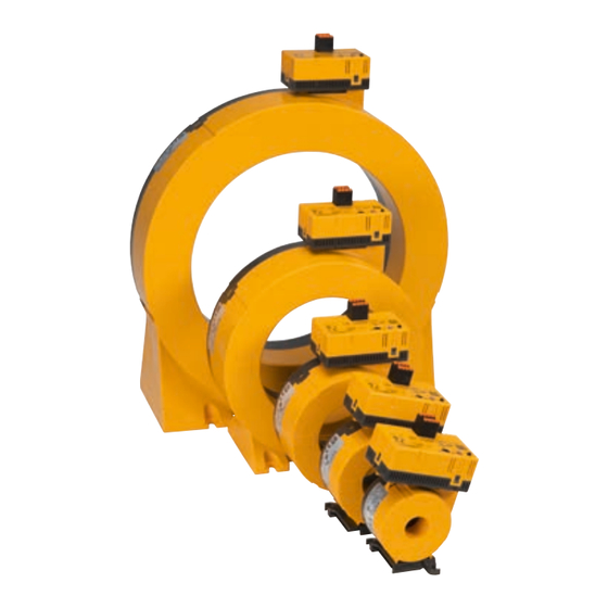
LINETRAXX® CTUB100 series
AC/DC sensitive measuring current transformers (type B)
Intended use
The AC/DC sensitive measuring current transformers (type
B) of the CTUB100 series convert system leakage and fault
currents into an evaluable measurement signal. The de-
vices are suitable for detecting fault currents with smooth
DC components. They consist of a CTBC... measuring cur-
rent transformer core and a CTUB10... electronic module,
which can be combined to suit the application. The meas-
uring current transformers can be used in DC, AC, and
3(N)AC systems. The measurement signal is evaluated us-
ing devices of the RCMA420/423, RCMS460/490, respec-
tively EDS440/441-LAB series, to which the measuring
current transformers are connected.
General safety instructions
Part of the device documentation in addition to this ma-
nual is the enclosed "Important safety instructions for
Bender products".
Installation, connection and commissioning are to be
carried out by electrically skilled persons only! It is es-
sential to follow the existing safety instructions.
I
! indicates a high risk of danger that will
D
anger
result in death or serious injury if not avoided.
I
! indicates a low-level risk that can result
C
aution
in minor or moderate injury or damage to proper-
ty if not avoided.
i
This symbol refers to information that is designed
to help you make the best use of the product.
Overview: Possible combinations of
evaluator, electronic module and measuring
current transformer core
Electronic modul
CTUB101
RCMS460/490*
RCMS460/490
CTUB102
CTUB104
EDS440/441-LAB
* Only recommended for retrofit if an AN420 power supply unit is already avai-
lable. In this case, if the ready-made connecting cable CTX... is used, the green
plugs of the connecting cable (on the evaluator side) must be removed.
CTUB100-series_D00362_02_M_XXEN / 08.2021
Evaluator
Meas. current transformer core
RCMA420
CTBC20(P)...60(P)
RCMA423
CTBC20(P)...210(P)
CTBC20(P)...210(P)
CTBC20(P)...210(P)
CTBC20(P)...60(P)
Device features
• Multicolour LED for operation, fault and status
messages
• Electronic module can be exchanged without
mechanical separation of the primary conductors
• Extension/retrofitting or modification of functio-
nalities possible in case of changed monitoring
requirements
• Insensitive to load currents due to full magnetic
shield, can be used for high short-term system-
related load currents (for CTBC...P only).
• Monitoring of the connection to the measuring
current transformer
Connecting cable
CTX... (6 wires)
CTX... (5/6 wires)
CTXS... (4 wires)
Afterwards, the individual conductors must be crimped and connected to the
RCMS460/490 or the AN420. In this case, the conductor "T" is not used
Supply voltage
DC ±12 V
The evaluator supplies the
measuring current transformer.
DC ±12 V
External power supply unit AN420
24 V
External power supply unit
Manual EN
Advertisement
Table of Contents

Subscribe to Our Youtube Channel
Related Manuals for Bender Linetraxx CTUB100 Series


Summary of Contents for Bender Linetraxx CTUB100 Series
- Page 1 Part of the device documentation in addition to this ma- nual is the enclosed "Important safety instructions for Device features Bender products". Installation, connection and commissioning are to be • Multicolour LED for operation, fault and status carried out by electrically skilled persons only! It is es- messages sential to follow the existing safety instructions.
-
Page 2: Dimension Diagrams
Dimension diagrams Dimensions (mm), Tolerance: ±0.5 mm Type CTUB…-CTBC20(P) ø 20 60.5 – CTUB…-CTBC35(P) ø 35 – CTUB…-CTBC60(P) ø 60 – CTUB…-CTBC120(P) ø 120 CTUB…-CTBC210(P) ø 210 CTUB – – Mountings (mm) Type CTBC20(P) 31.4 2 x ø 5.5 CTBC35(P) 49.8 2 x ø... -
Page 3: Device View
Device view CTUB101 CTUB102 CTUB104 Note S1 (k) Connection measuring current transformer core S2 (l) – Not in use – +12 V 24 V 24 V Supply voltage U -12 V – – – – Connection external test a) Offset calibration * Test button T b) Internal functional test ** Lights green normal operation... -
Page 4: Wiring Diagrams
E.01 (CT error) too high) clear the error by switching the device If the fault cannot be eliminated, contact Bender Service. off and on again Supply voltage U incorrect Apply correct supply voltage U (±12 V or 24 V) -
Page 5: Wiring Diagram
Wiring diagram CTBCx CTBCx CTUB102 CTUB101 CTUB104 S1(k) S2(l) S1(k) S2(l) +12V -12V T 24V GND to the loads to the loads 50 mm 50 mm 2,5 m CTXS-… 2,5 m CTX-… 10 m 10 m 250 mm 250 mm 24V GND RCMS460/490 Ext. -
Page 6: Technical Data
Installation instructions measuring current transformer ! Existing protective conductors and low-re- ! The measuring current transformer aution aution sistance conductor loops must not be routed must be connected to the corresponding evalua- through the measuring current transformer! tor before the first use and before commissio- Otherwise, high currents could be induced into the ning of the monitored installation. - Page 7 CTBC35 at I ≥ 30 mA ............125 A 80 A Classification of mechanical conditions acc. to IEC 60721 Δn Stationary use (IEC 60721-3-3) ............3M11 CTBC35 at I ≥ 300 mA ............. 160 A 125 A Δn Transport (IEC 60721-3-2) ..............2M4 CTBC35P ................
-
Page 8: Ordering Details
Nachdruck und Vervielfältigung Reprinting and duplicating nur mit Genehmigung des Herausgebers. only with permission of the publisher. Bender GmbH & Co. KG Bender GmbH & Co. KG Postfach 1161 • 35301 Grünberg • Deutschland PO Box 1161 • 35301 Grünberg • Germany Londorfer Str.
Need help?
Do you have a question about the Linetraxx CTUB100 Series and is the answer not in the manual?
Questions and answers