
Subscribe to Our Youtube Channel
Related Manuals for Bender LANTRAXX CMS460-D


Summary of Contents for Bender LANTRAXX CMS460-D
- Page 1 Manual CMS460-D Load current evaluators for 12 measuring channels for monitoring AC currents up to 125 A Software Version: D233 V2.42 / D256 V2.29 CMS460-D_D00045_01_M_XXEN/07.2016...
- Page 2 Bender GmbH & Co. KG P.O. Box 1161 • 35301 Gruenberg • Germany Londorfer Strasse 65 • 35305 Gruenberg • Germany Tel.: +49 6401 807-0 • Fax: +49 6401 807-259 E-Mail: info@bender.de • www.bender.de © Bender GmbH & Co. KG All rights reserved.
-
Page 3: Table Of Contents
Table of Contents 1. Important information ..................7 How to use this manual ................. 7 Technical support: service and support ........... 8 1.2.1 First level support ..................... 8 1.2.2 Repair service ..................... 8 1.2.3 Field service ......................9 Training courses ..................... 10 Delivery conditions .................. - Page 4 Table of Contents 4.3.4 Connection WF… series measuring current transformers ..... 24 4.3.5 Connection example CMS460 system with FTC470XET ....25 5. Commissioning ....................29 Before switching on ..................29 Switching on ....................30 6. Operation ......................31 Operator control and display elements ..........31 Working in operating mode ..............
- Page 5 Table of Contents 6.4.6.8 Settings menu 8: Interface ..............59 6.4.6.9 Settings menu 9: Alarm addresses ..........59 6.4.6.10 Settings menu 10: Clock ..............60 6.4.6.11 Settings menu 11: Password ............60 6.4.6.12 Settings menu 12: Factory settings ..........61 6.4.6.13 Settings menu 13: Service ..............
-
Page 7: Important Information
1. Important information 1.1 How to use this manual This manual is intended for qualified personnel working in electrical engineering and electronics! Always keep this manual within easy reach for future reference. To make it easier for you to understand and revisit certain sections in this man- ual, we have used symbols to identify important instructions and information. -
Page 8: Technical Support: Service And Support
Important information This manual has been compiled with great care. It might nevertheless contain errors and mistakes. Bender cannot accept any liability for injury to persons or damage to property resulting from errors or mistakes in this manual. 1.2 Technical support: service and support For commissioning and troubleshooting Bender offers you: 1.2.1... -
Page 9: Field Service
Important information Bender GmbH, Repair-Service, Londorfer Str. 65, 35305 Gruenberg 1.2.3 Field service On-site service for all Bender products Commissioning, configuring, maintenance, troubleshooting of Bender products Analysis of the electrical installation in the building (power quality test, ... -
Page 10: Training Courses
ZVEI (Zentralverband Elektrotechnik- und Elektronikindustrie e. V.) (German Electrical and Electron- ic Manufacturer's Association) also applies. Sale and delivery conditions can be obtained from Bender in printed or elec- tronic format. 1.5 Inspection, transport and storage Inspect the dispatch and equipment packaging for damage, and compare the contents of the package with the delivery documents. -
Page 11: Warranty And Liability
Important information 1.6 Warranty and liability Warranty and liability claims in the event of injury to persons or damage to property are excluded if they can be attributed to one or more of the follow- ing causes: Improper use of the device. ... -
Page 12: Disposal
13 August 2005 must be taken back by the manufacturer and disposed of properly. For more information on the disposal of Bender devices, refer to our homepage at www.bender-de.com -> Service & support. -
Page 13: Safety Instructions
2. Safety instructions 2.1 General safety instructions Part of the device documentation in addition to this manual is the enclosed "Safety instructions for Bender products". 2.2 Work activities on electrical installations Only qualified personnel are permitted to carry out the work necessary to install, commission and run a device or system. -
Page 14: Intended Use
Safety instructions 2.3 Intended use The CMS460-D load current evaluator is designed for the localisation of load currents up to 125 A in TT, TN and IT systems, AC 42…2000 Hz (measuring range see "chapter 8.1 Technical data", paragraph "Measuring circuit"). The CMS system consists of one or several CMS460-D load current evaluators which are able to detect and evaluate load currents in earthed and unearthed power supplies via the associated measuring current transformers. -
Page 15: System Description
3. System description In buildings and industrial installations, a fault or failure of the power supply involves high costs. In installations which require a high fault tolerance and good safety, an CMS460 system should constantly monitor the power supply for undercurrent and overcurrent. In addition, the CMS460-D can carry out an harmonics analysis for each channel. - Page 16 System description Two response values/common alarm relays, which can be set separately, al- low a distinction to be made between prewarning and alarm. The faulty chan- nel(s) and the associated measured value are indicated on the LC display. If the current falls below or exceeds the release value (response value plus hys- teresis), the release delay t begins.
- Page 17 System description Connecting measuring current transformers History memory The device utilises a history memory for failsafe storing of up to 300 data records (date, time, channel, event code, measured value), so that all data about an outgoing circuit or an area can be traced back at any time (what hap- pened when).
- Page 18 System description Analysis of harmonics The harmonic analysis of the measured currents can be selected via the menu item in the CMS460-D. There, the THF and the current value of the harmonics (1…40 at 50/60 Hz, 1…5 at 400 Hz) is displayed numerically and graphically. The total harmonic factor (THF) is expressed as the ratio of the harmonics r.m.s value of an alternating quantity to the r.m.s.
-
Page 19: Installation And Connection
Select the cables and cable lengths according to the technical data on page 71 ff. If you use cables that are longer than those specified here, Bender cannot guarantee that the equipment will function safely. For UL-application: ... -
Page 20: Installation Instructions
Installation and connection 4.2 Installation instructions The devices are suitable for the following installation methods: Distribution panels according to DIN 43871 or DIN rail mounting according to IEC 60715 Screw mounting using M4 screws. Mount the measuring current transformers in accordance with the notes in the "Transformer installation"... -
Page 21: Wiring Diagram
Installation and connection 4.3.2 Wiring diagram CMS460-D_D00045_01_M_XXEN/07.2016... - Page 22 Installation and connection Legend to wiring diagram A1, A2 Connection of the supply voltage U (see ordering informa- tion), fuse: 6 A fuse recommended. k1, l… Connection to measuring current transformers CT1…CT12. k12, l Measuring current transformers of the W…, WR…, WS… or WF…...
-
Page 23: Connection Of W
Installation and connection 4.3.3 Connection of W…, WR…, WS… series measuring current transformers Example: Connection W… series measuring current transformers The terminals 1 and 2 as well as the terminals 3 and 4 are bridged internally. The connections k and l on the load current evaluator must not be interchanged! CMS460-D_D00045_01_M_XXEN/07.2016... -
Page 24: Connection Wf
Installation and connection 4.3.4 Connection WF… series measuring current transformers CMS460-D_D00045_01_M_XXEN/07.2016... -
Page 25: Connection Example Cms460 System With Ftc470Xet
Installation and connection The connections k and l on the load current evaluator must not be interchanged! Legend to W…AB series measuring current transformer connec- tion W…F Flexible WF… series measuring current transformers RCC420 Signal converter Commercial measuring current transformers are not suitable for direct connection to the CMS460 system and must not be used. - Page 26 Installation and connection CMS460-D_D00045_01_M_XXEN/07.2016...
- Page 27 Installation and connection Legend to connection example CMS460-D Load current evaluators FTC470XET Protocol converter for connecting the BMS bus (Bender measuring device interface) with a TCP/IP (Transmission Control Protocol/Internet Protocol) network via Ether- net. DI-1PSM The DI-1PSM repeater only is required when the length of the cable exceeds 1200 m or when more than 32 devices are connected to the bus.
- Page 28 Installation and connection CMS460-D_D00045_01_M_XXEN/07.2016...
-
Page 29: Commissioning
5. Commissioning Opening the transparent front panel cover: Using the arrow on the bottom left-hand corner of the panel cover as a reference, lift the panel cover in an upward direction. The cover can also be removed completely. Refit the front panel cover as soon as the adjustments are completed. -
Page 30: Switching On
1. Connect the supply voltage of all devices connected to the BMS bus. Initially, the "ON" LED flashes on the CMS460-D and the graphic display shows the (Bender) welcome screen. The "ON" LED then lights up per- manently. 2. Set the BMS bus addresses. Never assign one address twice. Check, if address 001 and thus the master function has been assigned. -
Page 31: Operation
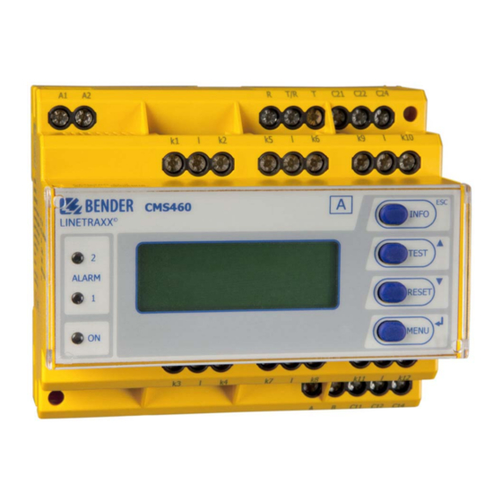
6. Operation 6.1 Operator control and display elements LED "ALARM 2" lights up if the measured value exceeds or falls below the response value "Alarm" on one channel. LED „ALARM 1“ lights up if the measured value exceeds or falls below the response value "Prewarning"... -
Page 32: Working In Operating Mode
Operation 6.2 Working in operating mode 6.2.1 Standard display In the operating mode, the CMS460-D displays a bar graph which shows what percentage of the of the set response value I (alarm) and I (prewarning) has been reached for each of the 12 measuring channels. . Channel disabled 100% (height = 1 graduation... - Page 33 Operation The CMS460-D signals prewarning and/or alarm: LED "ALARM 1" (prewarning) and/or LED "ALARM 2" (alarm) light depending on the type of alarm. Assigned common alarm relays (C…) switch. An alarm message is sent on the BMS bus. ...
-
Page 34: Test Procedure
Operation 6.2.3 Test procedure A test serves to check the device function (hardware components) of the CMS. There are different possibilities of starting a test: Select the standard display and press the "TEST" button on the front plate of the CMS460-for at least one second. Press an external test button connected to the CMS460-D. -
Page 35: Resetting Saved Alarm Messages (Reset)
Operation 6.2.4 Resetting saved alarm messages (RESET) If the fault memory is enabled, the alarm status will remain, even after the cause of the fault has been eliminated, until a "RESET" is carried out. First press the "ESC" button to exit the display of the current alarm message. The "RESET"... -
Page 36: Displaying Standard Information
Date of the measurement technique software version Line 6: Software version D256V… for communication processes Line 7: Date of communication software version Line 8…10: Bender address, homepage Line 11: Exit. Exit standard information. 6.3 Operation and setting 6.3.1 Opening the main menu Press the "MENU"... - Page 37 Settings can be password protected. When an attempt is made to change settings, the entry screen for entering the password appears automatically: Enter password: 0 0 0 Details see „Settings menu 11: Password“, page 60. If you can't remember your password, contact the Bender Service. CMS460-D_D00045_01_M_XXEN/07.2016...
-
Page 38: Menu Overview Diagram
Operation 6.3.2 Menu overview diagram CMS460-D_D00045_01_M_XXEN/07.2016... -
Page 39: Main Menu Functions
Operation 6.3.3 Main menu functions Menu item Function Page Exit Exit menu mode 1.Alarm/ Displays the following for each measuring meas.values channel, if applicable: Prewarning, alarm, measured value, response value, channel disa- bled. 2.% Bar graph The percentage of the total set alarm value I (alarm) and I (prewarning) which has been reached by each of the 12 measuring channels... -
Page 40: The Main Menu
Operation Menu item Function Page 8. External Settings on devices externally connected to devices the BMS bus (e.g. RCMS460-D/ -L, RCMS490-D/-L, CMS460-D). 9.Info Information about the device. The same dis- play is obtained by pressing the INFO button in the operating mode (see „Displaying standard information“... -
Page 41: Menu 2: % Bar Graph
Operation 6.4.2 Menu 2: % Bar graph For each of the 12 measuring channels the CMS460-D displays what percent- age of the total set alarm value has been reached. Channel disabled 100% (height =1 graduation mark) Channel enabled Channel enabled, Current is flowing k 1 2 3 4 5 6 7 8 9 10 11 12 (height ≥... - Page 42 Operation History no. 297 Start: 01.09.14 / 15:57:00 Ack: End: 01.09.14 / 16:07:03 Line 1: Event number (if applicable): TEST. Line 2: Start of the event: Date/time Line 3: Event acknowledgement (e.g. by pressing the "Buzzer off" button on PRC1470, TM…, MK2430, MK800): Date/time Line 4: End of the event: Date/time 1.
-
Page 43: Menu 4: Harmonics
Operation 6.4.4 Menu 4: Harmonics The analysis of the harmonics of the measured currents is displayed as a bar and a current value. Harmonics are multiples of the nominal frequency. Example: Rated frequency = 50 Hz, 2 harmonic = 100 Hz. CMS460-D can only determine the harmonic currents correctly if the rated fre- quency in menu "6.Settings ->... - Page 44 Operation Column 1: Displays the THF, DC component and the harmonic number. Column 2: Bar graph of the THF (% of the r.m.s value), bar graph of the current value. Column 3: Current r.m.s., THF/load current of this measuring channel. Harmonics current values are updated one after another.
-
Page 45: Menu 5: Data Logger
Operation 6.4.5 Menu 5: Data logger Up to 300 data records can be recorded for each of the 12 measuring chan- nels. A new measured value is stored if it differs from the previous measured value by a defined percentage. You define this percentage in menu "6.Set- tings->... -
Page 46: Menu 6: Settings
Operation 6.4.6 Menu 6: Settings The following menu items are available for configuring the CMS460-D: Menu item Function Page Exit Exit settings 1.General Set the fault memory, prewarning, hystere- sis, rated frequency and start-up delay. 2.PRESET Default setting of all response values to a selectable factor and offset value. -
Page 47: Settings Menu 1: General
Changing and activating the password. 12.Factory set- Resets all settings to factory settings. ting 13.Service For Bender service only. 6.4.6.1 Settings menu 1: General In this menu you make settings that apply to this device and therefore to all measuring channels. -
Page 48: Settings Menu 2: Preset
Operation 4.Frequency Select the rated frequency of the current being monitored. The correct fre- quency must be selected for the CMS460 to determine the harmonic current values properly. Setting options: DC, 50 Hz, 60 Hz, 400 Hz. 5.Start-up delay t (start-up) Time delay after switching the CMS460 on. - Page 49 Operation Exit 1.Factor: 2.Offset: 30 mA 3.PRESET 1.Factor (for PRESET) Set the multiplication factor for the latest measured value. Setting range: 1…99 %, resolution of setting 1 %. Recommended setting (factory setting): Factor 3 2.Offset (for PRESET) Set the offset value that is to be added to the product of the "current meas- ured value x factor".
-
Page 50: Settings Menu 3: Channel
Operation If the PRESET routine determines a value that exceeds the maximum response value (the highest possible response value is set). To prevent unwanted execution of this function, the entry must be confirmed once more. 6.4.6.3 Settings menu 3: Channel You make the measuring channel settings in this menu (either individually or for all channels (1…12) simultaneously). - Page 51 (wire up) Example 1: Bender measuring current transformers with a transformation ratio of 600/1 Factory setting: Factor: Example 2: The wire to be monitored is "wound" several times through the Bender cur- rent transformer in order to amplify the signal. CMS460-D_D00045_01_M_XXEN/07.2016...
- Page 52 Operation Setting: Factor: 2.Response value The response value is the value at which an alarm is output. For each measurement tolerances have to be considered (measuring current transformers, CMS460-D). According to IEC 62020, the set response value must not be exceeded. Therefore, the CMS460-D must be activated when 50…100 % of this value have been reached.
- Page 53 Operation Resolution of settings: Setting range Resolution of setting 100…200 mA 10 mA 250…500 mA 50 mA 600 mA… 2 A 100 mA 2.5 A…5 A 0.5 A 6 A…20 A 1.0 A 25 A…50 A 5.0 A 60 A…125 A 10.0 A 3.Function Monitoring the measuring channel for overcurrent or undercurrent.
- Page 54 Operation 60…200 s 10 s 250…500 s 50 s 600…999 s 100 (99) s 6.Cut-off frequency Set the characteristics for the frequency response of load current measure- ment I and current measurement I . Param. Objective 50 Hz Plant protection: Only evaluates the fundamental compo- nent of the current measurement.
- Page 55 Operation Frequency response (cut-off frequency) I(d) Response factor = I(dn) I(d) Load current: Currently measured r.m.s. value of the load current. I(dn) Rated operating current I : Set response value 7.Transformer Select the type of measuring current transformer. Type A Pulsating current sensitive W…, WR…, WS…...
-
Page 56: Settings Menu 4: Relays
Operation 6.4.6.4 Settings menu 4: Relays In this menu, you make the settings for the two common alarm relays K1 (C11, C12, C14) and K2 (C21, C22, C24) either individually or for both relays. Select the relay: 1. Use the arrow button "" to set the relay. Press the "↵" button. 2. -
Page 57: Settings Menu 5: History
Operation 2.Alarm Relay switches in the event of an alarm. Relay does not switch in the event of an alarm. 3.Prewarning Relay switches in the event of a prewarning. Relay does not switch in the event of a prewarning. 4.Device error Relay switches in the event of a device error Relay does not switch in the event of a device error. - Page 58 Operation Chan.:1 Exit 1.Modific.:10% 2.Overwrite:yes If the measuring channel settings only differ slightly, we recommend to proceed as follows: - first set all the measuring channels (1…12) to the same value - then modify the settings of an individual measuring channel 1.
-
Page 59: Settings Menu 7: Language
Operation 6.4.6.7 Settings menu 7: Language Select the language for the menu and the alarm texts. Setting options: English, Deutsch or Français. 6.4.6.8 Settings menu 8: Interface Set the BMS bus address of the CMS460-D. The device with address 1 has the master function on this bus. -
Page 60: Settings Menu 10: Clock
Operation 6.4.6.10 Settings menu 10: Clock Set the date format, date, time, and summer time changeover. Set the time and date on the BMS bus master (addr. 1). This setting is applied to all slaves. The setting is synchronised every hour. The "Clock"... -
Page 61: Settings Menu 12: Factory Settings
Once a valid password has been entered, access will be given to settings in all menus (except the Service menu) until the menu mode is exited. If you can't remember your password, contact the Bender Service. 6.4.6.12 Settings menu 12: Factory settings Resets every setting to factory setting. -
Page 62: Menu 7: Control
Operation 6.4.7 Menu 7: Control This menu offers various options for controlling the CMS: Exit Exit settings 1.TEST Call a test 2.RESET Call a reset 3.Test Test communication between the CMS460-D communication and other BMS devices. 6.4.7.1 Control menu 1: TEST Call a test (also refer to „Test procedure“... - Page 63 Operation Channel disabled Exit 1.Chan.: 1. Use the arrow button "" to set the measuring channel. Press the "↵" button. 2. Use the Up/Down buttons to select a measuring channel. Press the "↵" button to confirm your selection. The alarm is sent on the BMS bus. This is presented by the alarm indication .
-
Page 64: Menu 8: External Devices
Operation 6.4.8 Menu 8: External devices This menu can be used for setting and operating external devices connected via the BMS bus to this CMS460-D. In this way, for example, RCMS460-L or other CMS460-devices can be set. The menu options of the external devices available via this function are indicated in the CMS460-D display. -
Page 65: Menu 9: Info
Operation If "no access to the menu" appears, press the "ESC“ button to exit the display. Possible causes are: No device with this address available. Connected device does not support this programming function. Access not possible at the moment. ... - Page 66 Operation CMS460-D_D00045_01_M_XXEN/07.2016...
-
Page 67: Tests, Service, Troubleshooting
7.2 Maintenance and service The CMS460 system does not contain any parts that must be maintained. For commissioning, Bender also offers on-site service and training courses. Please contact our Service Department for more information. You will find the address on page 10 of this manual. - Page 68 Tests, service, troubleshooting Error Description code Measurement technique: Fault parameter memory (EEPROM/FLASH) Measurement technique: Fault data memory (RAM) Measurement technique: No boot loader available Measurement technique: Device not calibrated Measurement technique: Wrong measurement p.c.b., incor- rect mounting. Measurement technique: Hardware error after performing a self test.
-
Page 69: Device Error Display (Channel-Related)
Tests, service, troubleshooting 7.3.2 Device error display (channel-related) LED "ALARM 1“ lights up. The programmed common alarm relay switches. The following test is shown on the display of the CMS460-D: Fault Device error Addr.: 2 Channel: 4 Line 1: FAULT, Alarm 1 of 1 pending alarms Line 2: Alarm status and alarm text No alarm... - Page 70 Tests, service, troubleshooting CMS460-D_D00045_01_M_XXEN/07.2016...
-
Page 71: Data
8. Data 8.1 Technical data Insulation coordination acc. to IEC 60664-1/IEC 60664-3 for the versions: a)CMS460-D1 Supply voltage U ................DC 24…75V / AC 24…60 V (AC/DC ±20 %) Supply voltage frequency........................... DC, 50/60 Hz Rated insulation voltage............................100 V Overvoltage category/pollution degree........................ - Page 72 Data b) CMS460-D2 Supply voltage U ....................AC/DC 100…240 V (-20…+15 %) Supply voltage frequency ...........................DC, 50/60 Hz Rated insulation voltage............................250 V Overvoltage category/pollution degree........................III/3 Rated impulse voltage ............................. 6 kV Protective separation (reinforced insulation) between......... (A1, A2) - (k1, l…k12, R, T/R, T, A, B), (C11, C12, C14), (C21, C22, C24), (11,14), (21,24), (31,34), (41,44), (51,54), (61,64), (71,74), (81,84), (91,94),(101,104), (111,114), (121,124) Protective separation (reinforced insulation) between.........(C11, C12, C14) - (C21, C22, C24) -...
- Page 73 Data Relative uncertainty ..........................+10…-20 % Hysteresis ............................2…40% (20 %)* Factor for additional CT ....................../2…10; x 1…10 (x 1)* Number of measuring channels (per device/system)..................12/1080 Time response Start-up delay t per device ..................... 0…99 s (0 ms)* (start-up) Response delay t per channel ....................0…999 s (200 ms)* Delay on release t per channel....................0…999 s (200 ms)*...
- Page 74 Data Terminating resistor ..................120 Ω (0.25 W) connectable via DIP switch Device address, BMS bus ..........................1…90 (2)* Cable lengths for W…, WR…, WS…, WF… series measuring current transformers Single wire ≥ 0.75 mm ........................... 0…1 m Single wire, twisted ≥ 0.75 mm ........................
- Page 75 Data Connection screw-type terminals Connection properties: Rigid/flexible/conductor sizes..............0.2…4 / 0.2…2.5 mm /AWG 24…12 Multi-conductor connection (2 conductors with the same cross section): Rigid/flexible........................0.2…1.5 / 0.2…1.5 mm Stripping length............................. 8…9 mm Tightening torque............................. 0.5…0.6 Nm Other Operating mode ..........................continuous operation Mounting ...............................display-oriented Degree of protection, internal components (IEC 60529) ..................
-
Page 76: Standards, Approvals, Certifications
Data 8.2 Standards, approvals, certifications Standards Observe the applicable national and international standards. DIN EN 62020 (VDE 0663):2005-11 IEC 62020 (2003-11) Ed. 1.1.. The operating manuals for the individual system components provide you with information about the standards that apply to that particular device. 8.3 Ordering information Load current evaluators Supply voltage U... - Page 77 Supply voltage U */Description Type Art. No. COM460IP BMS-Ethernet-Gateway for the connec- B 9506 1010 tion of the Bender measuring device inter- face to TCP/IP networks AC/DC 76…276 V */ AC 42…460 Hz/DC COM460IP-24 V BMS-Ethernet Gateway B 9506 1020 DC 16…94 V...
- Page 78 Data Supply voltage U */Description Type Art. No. COM460IP- BMS-Ethernet Gateway; B 9506 1012 Option B Modbus/TCP server with max. 14700 BMS nodes COM460IP- BMS-Ethernet Gateway; B 9506 1013 Option C Parameter setting for BMS devices COM460IP- BMS-Ethernet Gateway; Visualisation of B 9506 1014 Option D BMS devices...
- Page 79 Data Supply voltage U */Description Type Art. No. MK2430-11 Alarm indicator and test combination in B 9510 0001 accordance with IEC 60364-7-710, with BMS bus and USB interface, 12 digital inputs, one relay output, alarm texts pro- grammable via interfaces and personal computer, standard text display.
- Page 80 MK2430S-12 As MK2430-12, but front plate with screw B 9510 0012 fixing * Absolute values ** Other versions on request Pulsating current sensitive measuring current transformers Bender measuring current transformers Inside Type Design type Art. No. diameter/mm circular B 9808 0003...
- Page 81 Data Flexible measuring current transformers (pulsed DC sensitive) WF… series measuring current transformers consist of one flexible W…F se- ries measuring current transformer and one RCC420 signal converter. Inside Supply Type Art. No. diameter/mm voltage WF170-1 DC 9.6…94 V / B 7808 0201 AC 42…460 Hz 16…72 V...
- Page 82 Data Inside Supply Type Art. No. diameter/mm voltage WF1200-1 1200 DC 9.6…94 V / B 7808 0209 AC 42…460 Hz 16…72 V WF1200-2 1200 DC 70…300 V / B 7808 0210 AC 42…460 Hz 70…300 V Measuring current transformers accessories Type Art.
-
Page 83: Index
Fuses 19 Alarm status 33 alternating currents 14 Harmonic 14 High fault tolerance 15 Bar graph 32 History memory 41 Bender service 61 How to use this manual 7 Bus address 59 Hysteresis 47 Commissioning 29 Installation 19 Connection 19... - Page 84 Ordering information 76 Time 60 Overcurrent 53 Training courses 10 Overview diagram 38 Transformation ratio 51 Transformer monitoring 55 Password 60 presetting 48 Undercurrent 53 Prewarning 33 Property protection 54 Wiring diagram 22 Protection against fire 54 Work activities on electrical installations 13 pulsating currents 14 workshops 10 r.m.s.
- Page 88 Bender GmbH & Co. KG P.O. Box 1161 • 35301 Gruenberg • Germany Londorfer Strasse 65 • 35305 Gruenberg • Germany Tel.: +49 6401 807-0 • Fax: +49 6401 807-259 E-Mail: info@bender.de • www.bender.de Group Photos: Bender archives...
Need help?
Do you have a question about the LANTRAXX CMS460-D and is the answer not in the manual?
Questions and answers