Bender COMTRAXX COM465IP Manual
Condition monitor with integrated gateway for the connection to profibus dp and ethernet-tcp/ip networks
Hide thumbs
Also See for COMTRAXX COM465IP:
- Quick start (4 pages) ,
- Quick start manual (9 pages) ,
- Manual (64 pages)

Subscribe to Our Youtube Channel
Related Manuals for Bender COMTRAXX COM465IP


Summary of Contents for Bender COMTRAXX COM465IP
- Page 1 Manual COMTRAXX® COM465IP/COM465DP Condition Monitor with integrated Gateway for the connection of Bender devices to PROFIBUS DP and Ethernet-TCP/IP networks Software version: D472 V2.0x COM465IP-COM465DP_D00216_02_M_XXEN/03.2017...
- Page 2 Bender GmbH & Co. KG © Bender GmbH & Co. KG All rights reserved. P.O. Box 1161 • 35301 Gruenberg • Germany Londorfer Straße 65 • 35305 Gruenberg • Germany Reprinting only with permission Tel.: +49 6401 807-0 • Fax: +49 6401 807-259 of the publisher.
-
Page 3: Table Of Contents
Table of Contents 1. Important information ................... 7 How to use this manual ......................7 Technical support: service and support ................8 1.2.1 First level support ........................8 1.2.2 Repair service ..........................8 1.2.3 Field service ..........................9 Training courses ........................9 Delivery conditions ......................... - Page 4 Table of Contents 3.6.2 Process image ......................... 18 3.6.3 List of BMS devices compatible with the COM465… ..........18 BMS side of the COM465… ....................18 4. Installation, connection and commissioning ..........19 Preliminary considerations ....................19 Installation and connection ....................20 Installing device ........................
- Page 5 Table of Contents 6.1.1 Exception code ........................39 6.1.2 Modbus requests ........................39 6.1.3 Modbus responses ....................... 40 6.1.4 Structure of the exception code ..................40 6.1.5 Modbus address structure for BMS devices ..............40 Modbus process image in the memory of the COM465… ........41 6.2.1 Querying data ........................
- Page 6 Table of Contents Tabular data ..........................61 Standards, approvals and certificates ................63 Ordering data .......................... 64 INDEX ........................... 65 COM465IP-COM465DP_D00216_02_M_XXEN/03.2017...
-
Page 7: Important Information
– the properties of the gateways COMTRAXX® COM465IP and COMTRAXX® COM465DP, – the connection of the devices – and the PROFIBUS DP interface of the COMTRAXX® COM465DP. The "COMTRAXX" manual. It describes the functions of the web user interface for Bender gateways. -
Page 8: Technical Support: Service And Support
Although great care has been taken in drafting this manual, it may nevertheless contain errors and mistakes. Bender cannot accept any liability for injury to persons or damage to property resulting from errors or mistakes in this manual. -
Page 9: Field Service
**Mo-Thu 7.00 a.m. - 8.00 p.m., Fr 7.00 a.m. - 13.00 p.m. 1.3 Training courses Bender is happy to provide training regarding the use of test equipment. The dates of training cours- es and workshops can be found on the Internet at www.bender-de.com -> Know-how -> Seminars. -
Page 10: Inspection, Transport And Storage
1.5 Inspection, transport and storage Inspect the dispatch and equipment packaging for damage, and compare the contents of the pack- age with the delivery documents. In the event of damage in transit, please contact Bender immedi- ately. The devices must only be stored in areas where they are protected from dust, damp, and spray and dripping water, and in which the specified storage temperatures can be ensured. -
Page 11: Safety Instructions
The gateway connects the following devices to Ethernet TCP/IP and PROFIBUS DP networks: Bender devices with BMS bus or BCOM interface Bender universal measuring devices PEM… with Modbus RTU or Modbus TCP. The COM465… converts alarms, measured values and statuses from the devices to the Modbus TCP and HTTP protocols. -
Page 12: Address Configuration And Termination
Safety instructions 2.4 Address configuration and termination To ensure the correct function of the COM465…, correct address assignment and termination is of utmost importance. Malfunction due to duplicated addresses! The duplicate assignment of addresses can cause serious malfunctions in the bus systems affected. -
Page 13: Product Description
BUS DP. 3.2.1 Functional scope of COM465IP and COM465DP basic device (without function modules) Condition Monitor with a web interface for use with Bender BMS and BCOM devices and univer- sal measuring instruments. Support for devices that are connected to ... -
Page 14: Function Module A
Product description Setting internal parameters and the configuration of Bender Universal measuring instruments and energy meters.** Time synchronisation for all assigned devices History memory (1,000 entries) Data logger, freely configurable (30 * 10,000 entries) Documenting the device: A PDF file to document the settings of the used COMTRAXX device ... -
Page 15: Function Module C
3.3 Applications Optimum display and visualisation of device and plant statuses in the web browser Observing and analysing compatible BENDER products (ISOMETER®, ATICS®, RCMS, EDS, Line- traxx® and MEDICS systems, universal measuring devices and energy meters) Specific system overview according to individual installation description ... -
Page 16: Function
The COM465… are integrated into the existing EDP structure like PCs. After connecting to the net- work and compatible Bender products, all system devices can be accessed from any PC using a standard web browser (e.g. Google Chrome, Mozilla Firefox, Internet Explorer). In this way, all impor- tant system information is directly available. -
Page 17: Description Of Function
BCOM for new and future Bender systems, e.g. ISOMETER® iso685-D. Modbus RTU (RS-485) COM465… on operation as a master for Bender universal measuring devices PEM..3 and also PEM..5 with restricted functionality (full functionality of PEM..5 only via Modbus TCP). -
Page 18: Process Image
Internal and external BMS bus The majority of Bender devices communicate via the internal BMS bus. Individual devices, such as MK800, TM 800 or Bender panels can communicate via both the internal BMS bus (BMS i) and the ex- ternal BMS bus (BMS e). -
Page 19: Installation, Connection And Commissioning
You will find more detailed information on the topic of BMS, in particular about the wiring of bus devices, in the separate document "BMS bus". You can obtain this document at: http:// www.bender.de > Service & support > Download > Operating manuals. 3. Does the computer network have a DHCP server? Otherwise, the network data allocated by the person responsible for the installation such as the IP address and subnet mask must be set manually. -
Page 20: Installation And Connection
Installation, connection and commissioning 4.2 Installation and connection Only qualified personnel are permitted to carry out the work necessary to in- stall, commission and run a device or system. Mortal danger due to electric shock! Touching live parts of the system carries the risk of: An electric shock ... -
Page 21: Connecting Device
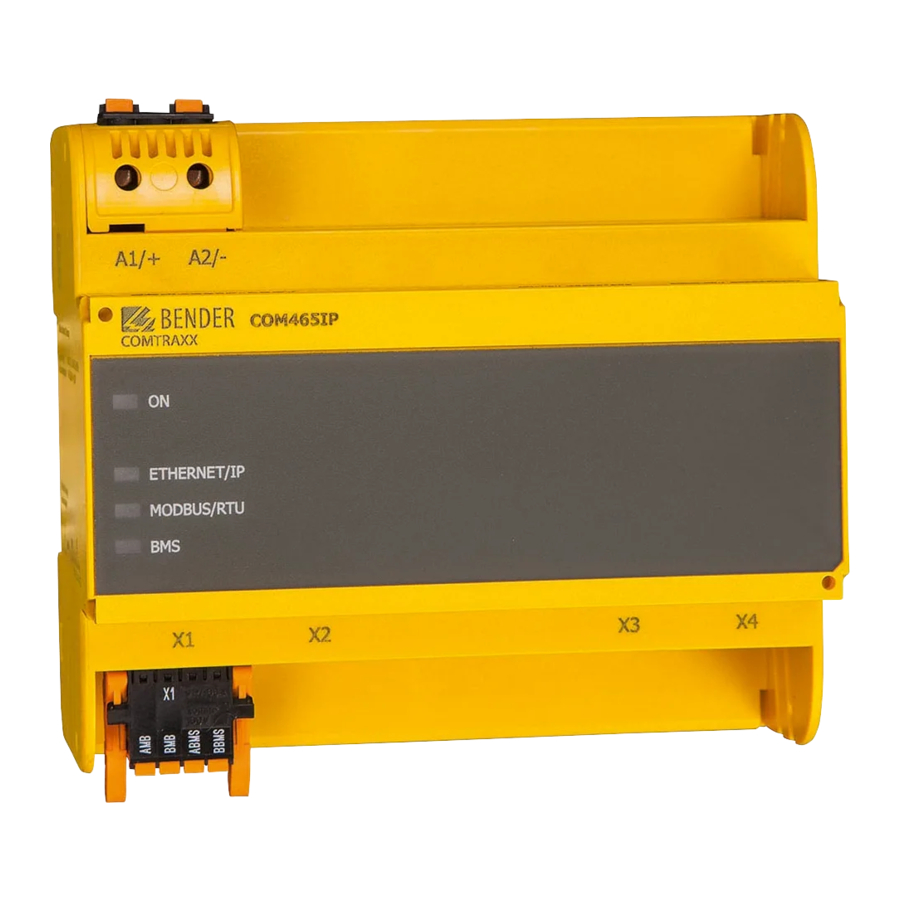
PROFIBUS DP connection (COM465DP only) Modbus/RTU interface: Terminals AMB and BMB Plug X1 BMS bus (Bender measuring device interface): Terminals ABMS and BBMS Ethernet connection (RJ45) for the connection to the PC network as well as to Plug X2 BCOM... -
Page 22: Displays And Controls
Installation, connection and commissioning 5. PROFIBUS DP connection (COM465DP only): Connect the corresponding connector on the PROFIBUS cable to the 9-pin Sub-D socket (2). If the COM465DP is at the end of the PROFIBUS DP network, you must switch the terminating switch on the PROFIBUS connector to "ON". -
Page 23: Placing Device In Operation
Risk of duplicate addresses if BCOM system name is not changed. The factory setting for the system name on all Bender BCOM devices is "SYSTEM". If several systems are established in the same network, there is a risk that ad- dresses will be assigned more than once. -
Page 24: Addresses And Their Factory Settings
It describes in a standardised format the properties of the COM465DP. You can obtain the latest GSD file at: http://www.bender.de > Service & support > Download > Software 1. Select the destination folder to which the GSD file is to be copied. For the exact destination please see the documentation for the program you want to use to program the PROFIBUS mas- ter. -
Page 25: Profibus Dp (Com465Dp Only)
The gateway and its PROFIBUS address are to be made known to the PROFIBUS master. For this pur- pose you will need the file BEND0F27.gsd (see "Scope of delivery" on page 13) A connection from Bender systems with BMS bus and BCOM to PROFIBUS DP using COM465DP can be necessary for various reasons: A PROFIBUS DP device is to react to an event in the BMS world ... -
Page 26: Correct Control Of The Timing On The Com465Dp Using Profibus Commands Is Necessary
PROFIBUS DP (COM465DP only) 5.1.2 Correct control of the timing on the COM465DP using PROFIBUS commands is necessary. Due to the different times the various devices take to respond to the commands, it may occur that responses from previous queries arrive between a query from the PROFIBUS DP master and the re- lated response from the slave, (COM465DP). -
Page 27: Data Access Using Profibus Dp
PROFIBUS DP (COM465DP only) 5.1.5 Data access using PROFIBUS DP PROFIBUS DP offers three methods for reading or writing data: – Type 1: Querying measured data from devices on the bus – Type 2: Querying registers in devices on the bus –... -
Page 28: Type 2: Querying Registers In Devices On The Bus
PROFIBUS DP (COM465DP only) Byte 6: Structure of the byte: Range and unit. For details see "R&U = Range and unit" on page 46. Range validity State Unit Byte 7: Description high: The high byte of the measured value description. For details see "Channel descriptions for the process image"... -
Page 29: Type 3: Writing To Registers On Devices On The Bus
PROFIBUS DP (COM465DP only) Response from the gateway: Byte 0 Byte 1 Byte 2 Byte 3 Byte 4 Byte 5 Byte 6 Byte 7 Byte 8 Byte 9 Numb Reg. 0 Reg. 0 Reg. 1 Reg. 1 Reg. 2 Reg. 2 Reg. - Page 30 PROFIBUS DP (COM465DP only) Response from the gateway: Byte 0 Byte 1 Byte 2 Byte 3 Byte 4 Byte 5 Byte 6 Byte 7 Byte 8 Byte 9 Number 0xFF 0xFF 0xFF 0xFF 0xFF 0xFF 0xFF 0xFF of regis- ters Byte 0: Sequential ID no.
-
Page 31: Programming Examples
BEND0F27.gsd before executing the program. You can download the latest gsd file from the following address on our web site: http://www.bender.de > Service & support > Download > Software 5.2.1 Type 1: Querying measured data from devices on the bus 5.2.1.1... - Page 32 PROFIBUS DP (COM465DP only) Response from the gateway: Byte 0 Byte 1 Byte 2 Byte 3 Byte 4 Byte 5 Byte 6 Byte 7 Byte 8 Byte 9 Data Data Data Data value value value value Alarm Range Descrip- Descrip- 0xFF high high...
-
Page 33: Example 2: Querying Measured Value In The Event Of An Irdh375 Alarm
PROFIBUS DP (COM465DP only) 5.2.1.2 Example 2: Querying measured value in the event of an IRDH375 alarm The IRDH375 has the BMS address 3, channel 1 is queried. An insulation fault with the measured value 5 kΩ has occurred (alarm). Request to the gateway Byte 0 Byte 1... - Page 34 PROFIBUS DP (COM465DP only) Response from the gateway: Byte 0 Byte 1 Byte 2 Byte 3 Byte 4 Byte 5 Byte 6 Byte 7 Byte 8 Byte 9 Data Data Data Data value value value value Alarm Range Descrip- Descrip- 0xFF high high...
-
Page 35: Example 3: Querying Irdh375 Device Fault
PROFIBUS DP (COM465DP only) 5.2.1.3 Example 3: Querying IRDH375 device fault The IRDH375 has the BMS address 3, channel 4 is queried. There is an "earth connection" device fault. Request to the gateway Byte 0 Byte 1 Byte 2 Byte 3 Byte 4 Byte 5 Byte 6... - Page 36 PROFIBUS DP (COM465DP only) Response from the gateway: Byte 0 Byte 1 Byte 2 Byte 3 Byte 4 Byte 5 Byte 6 Byte 7 Byte 8 Byte 9 Data Data Data Data value value value value Alarm Range Descrip- Descrip- 0xFF high high...
-
Page 37: Type 2: Querying Registers In Devices On The Bus
PROFIBUS DP (COM465DP only) 5.2.2 Type 2: Querying registers in devices on the bus 5.2.2.1 Example: Querying a register on the RCMS490-D The RCMS490-D has the BMS address 2. The "Prewarning" menu item is queried. It has the value "50 %". -
Page 38: Type 3: Writing To Registers On Devices On The Bus
PROFIBUS DP (COM465DP only) 5.2.3 Type 3: Writing to registers on devices on the bus 5.2.3.1 Example: Writing to a register on the RCMS490-D The RCMS490-D has the BMS address 2. The "Prewarning" menu item is written. It has the value "50 %". -
Page 39: Modbus Tcp Server
6. Modbus TCP server 6.1 Data access using Modbus TCP protocol Requests are sent to the Modbus TCP server in the COM465… using function code FC4 (read input register). The server generates a function-related response and sends it to the Modbus client. 6.1.1 Exception code If a request cannot be answered for whatever reason, the server sends a so-called exception code... -
Page 40: Modbus Responses
Modbus TCP server 6.1.3 Modbus responses The responses consist of 2 bytes per register. The MSB is the first byte. Byte Name Example … … … Byte 7 MODBUS function code 0x04 Byte 8 Byte count 0x04 Byte 9, 10 Value register 0 0x1234 (fictitious value) Byte 11, 12... -
Page 41: Modbus Process Image In The Memory Of The Com465
Modbus TCP server 6.2 Modbus process image in the memory of the COM465… The device holds a process image in memory. This image represents the current states and values of all devices that are in the same system as the COM465… 6.2.1 Querying data 6.2.1.1... -
Page 42: Memory Scheme Of The Process Image
Modbus TCP server 6.2.2 Memory scheme of the process image 6.2.2.1 Structure of the process image As illustrated in the table, the Modbus start address for the respective process image is derived from the device address. 256 (0x100) words or 512 bytes are reserved for each device. They contain all the information requested and transmitted from the bus. - Page 43 Modbus TCP server Example: Channel 2 of the device with address 3 is to be queried. How is the start address determined to send the query for the channel? In our example, the relevant cells in the table are marked in bold. 1.
-
Page 44: Device Type
Modbus TCP server 6.2.2.3 Device type Word 0x01 0x02 0x03 0x04 0x05 0x06 0x07 0x08 0x09 0x00 ASCII text, 10 words/20 bytes The device type is set using a bus scan. 6.2.2.4 Timestamp Word 0x0A 0x0B 0x0C 0x0D HiByte LoByte HiByte LoByte HiByte... -
Page 45: Float = Floating Point Value Of The Channels
Modbus TCP server 6.2.2.7 Float = Floating point value of the channels Word 0x00 0x01 Byte HiByte LoByte HiByte LoByte 31 30 24 23 22 16 15 S E E E E E E E E M M M M M M M M M M M M M M M M M M M M M M M Representation of the bit order for processing analogue measured values according to IEEE 754 S = Sign E = Exponent... -
Page 46: R&U = Range And Unit
Modbus TCP server 6.2.2.9 R&U = Range and unit Meaning Invalid (init) No unit Ω Baud °C °F Second Minute Hour Month X … … … … … Reserved CODE Reserved X … … … … … Reserved Reserved True value True value is smaller True value is larger Invalid value... -
Page 47: Channel Description
Modbus TCP server 6.2.2.10 Channel description Word 0x03 deci- Byte Meaning HiByte LoByte 15 14 13 12 11 10 9 Reserved Insulation fault Overload Overtemperature Failure Line 1 Failure Line 2 Insulation OP light Reserved Distribution board failure Oxygen Vacuum Anaesthetic gas Compressed air 5 bar …... -
Page 48: Channel 33 To 64
Modbus TCP server 6.2.2.11 Channel 33 to 64 Meaning No alarm Prewarning Device error Reserved Alarm (yellow LED), e.g. insulation fault Alarm (red LED) Reserved X … … … Reserved Reserved No test Internal test External test The channels 33 to 64 only provide digital information. The information is coded as an alarm or mes- sage type or test type (internal, external). -
Page 49: Modbus Examples To Read Out Data
Modbus TCP server 6.2.3 Modbus examples to read out data Example: Reading out from ATICS channel 1 (voltage line 1) COM465… has address 1 in subsystem 1. ATICS channel 1 of internal address 3 is to be read out. The content is the voltage of line 1 as floating point value. -
Page 50: Reference Data Records Of The Process Image
Modbus TCP server 6.2.4 Reference data records of the process image To make it easier to check the configuration and the Modbus TCP data access to devices, the COM465… provides a reference data record at the virtual address 0. No real device can have address 0! Address 0 only serves to simulate data access. -
Page 51: Reference Value On Channel 2
Modbus TCP server 6.2.4.3 Reference value on channel 2 The following reference value is stored in this channel:12.34 A Word 0x14 0x15 0x16 0x17 HiByte LoByte HiByte LoByte HiByte LoByte HiByte LoByte 0x41 0x45 0x70 0xA4 0x00 0x03 0x00 0x4A Floating point value AT&T R&U... -
Page 52: Channel Descriptions For The Process Image
Modbus TCP server 6.2.5 Channel descriptions for the process image Measured value description alarm Value Note message operating message 1 (0x01) Insulation fault 2 (0x02) Overload 3 (0x03) Overtemperature 4 (0x04) Failure line 1 5 (0x05) Failure line 2 6 (0x06) Insul. - Page 53 Modbus TCP server Measured value description alarm Value Note message operating message 40 (0x28) Failure UPS Battery-supported safety power supply 41 (0x29) 66 (0x42) 67 (0x43) Function test till: Date 68 (0x44) Service till: Date 69 (0x45) Ins.fault locat Insulation fault location 70 (0x46) Peak Fault EDS system...
- Page 54 Modbus TCP server Measured value description alarm Value Note message operating message 108 (0x6C) Fault contactor K2 109 (0x6D) 110 (0x6E) 111 (0x6F) No address: Failure BMS device 112 (0x70) 113 (0x71) Failure K1/Q1 Failure contactor K1/Q1 114 (0x72) Failure K2/Q2 Failure contactor K2/Q2 115 (0x73) Device error...
- Page 55 Modbus TCP server Measured value description alarm Value Note message operating message 203 (0xCB) Switch. el. 1 on 204 (0xCC) Switch. el. 2 on 205 (0xCD) 206 (0xCE) Auto mode 207 (0xCF) Manual mode 208 (0xD0) 209 (0xD1) 210 (0xD2) Line AV on 211 (0xD3) Line SV on...
-
Page 56: Modbus Control Commands
Modbus TCP server Value Description of parameters: 1008 (0x3F0) Factor division [/] 1007 (0x3EF) Baud rate 6.2.6 Modbus control commands Commands can be sent to BMS devices by an external application (e.g. data display software). This functionality can be activated or deactivated via the web user interface. Command structure Write Read... - Page 57 Modbus TCP server Control commands for the internal and external BMS bus int/ext Register Register Register Register Menu text/ Channel command Function 1-150 Test Isometer 1-99 Test changeover unit (PRC487) / 1-150 Test Umschalteinrichtung PRC 1-99 1-150 Test changeover unit (ATICS) / Start automatischer Test Umschaltung 1->2 Ende nach der Zeit T(Test)
-
Page 58: Modbus Example For Control Commands
Modbus TCP server 6.2.6.1 Modbus example for control commands Example: Changeover of ATICS to line 1 COM465… has address 1 in subsystem 1. An ATICS of internal address 3 is to be changed over to line Modbus control command:00 02 00 00 00 0F 01 10 FC 00 00 04 08 00 01 00 03 00 00 00 05 00 02 Transaction ID (is generated automatically) 00 00... -
Page 59: Troubleshooting
Use the backup function to save all settings of the device (see chapter "3.2 Device features" as well as the COMTRAXX® manual). Frequently asked questions in the Internet You will find FAQs on many Bender devices at: http://www.bender.de > Service & support > Rapid assistance > FAQ COM465IP-COM465DP_D00216_02_M_XXEN/03.2017... -
Page 60: Maintenance
Troubleshooting 7.2 Maintenance The device does not contain any parts that must be maintained. 7.3 Cleaning The device is only allowed to be cleaned using a clean, dry, soft, antistatic cloth. COM465IP-COM465DP_D00216_02_M_XXEN/03.2017... -
Page 61: Technical Specifications
8. Technical specifications 8.1 Tabular data ( )* = Factory setting Insulation coordination in acc. with IEC 60664-1/IEC 60664-3 (For 230 V variants B95061060) Rated voltage................................ AC 250 V Rated impulse withstand voltage/overvoltage category ..................4 kV / III Pollution degree ................................3 Safe isolation (reinforced insulation) between ...............(A1/+, A2/-) - [(AMB, BMB), (ABMS, BBMS), (X2), (X3, X4), (PROFIBUS DP)] Insulation coordination in acc. - Page 62 Terminating resistor .................120 Ω (0.25 W), can be switched on internally Device address, BMS bus internal/external ....................1…99 (1)* BCOM Interface/protocol ............................Ethernet/BCOM BCOM system name............................(BENDER)* BCOM subsystem address..........................1…99 (1)* BCOM device address............................1…99 (1)* Modbus TCP Interface/protocol ........................... Ethernet/Modbus TCP Operating mode ..................
-
Page 63: Standards, Approvals And Certificates
Technical specifications Climate classes acc. to IEC 60721: Stationary use (IEC 60721-3-3) ............3K5 (except condensation and formation of ice) Transport (IEC 60721-3-2) ............................2K3 Long-term storage (IEC 60721-3-1) ........................... 1K4 Mechanical conditions acc. to IEC 60721: Stationary use (IEC 60721-3-3) ..........................3M4 Transport (IEC 60721-3-2) ............................ -
Page 64: Ordering Data
Parameter setting for BMS devices as well as BCOM and uni- Function module C versal measuring devices, generating and importing backup B 7506 1013 files Function module D Visualisation of Bender systems, system visualisation B 7506 1014 Function module E Virtual devices B 7506 1015 Function module F... -
Page 65: Index
INDEX Workshops 9 Address 24 Malfunctions 59 Manual 7 Measured value descriptions for the proc- ess image, list 52 BMS device address assignment on the Memory image of a BMS device 43 Modbus 42 Memory scheme of the process image 42 Byte offset 51 Modbus Byte or word swapping 51... - Page 66 INDEX COM465IP-COM465DP_D00216_02_M_XXEN/03.2017...
- Page 68 Bender GmbH & Co. KG P.O. Box 1161 • 35301 Gruenberg • Germany Londorfer Straße 65 • 35305 Gruenberg • Germany Tel.: +49 6401 807-0 • Fax: +49 6401 807-259 E-mail: info@bender.de • www.bender.de Fotos: Bender Archiv.
Need help?
Do you have a question about the COMTRAXX COM465IP and is the answer not in the manual?
Questions and answers